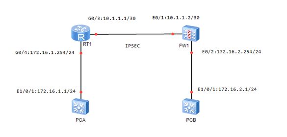
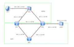
The topology is as shown in the figure ↓
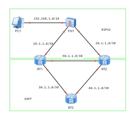
After the IP/protocol is configured, the routing of each device is shown in the figure ↓
FW1 H>* 1.1.1.1/32 [0/0/1] is local address, loopback1 C>* 10.1.1.0/30 is directly connected, ethernet0/1 H>* 10.1.1.1/32 [0/0/1] is local address, ethernet0/1 C>* 20.1.1.0/30 is directly connected, ethernet0/2 H>* 20.1.1.1/32 [0/0/1] is local address, ethernet0/2 C>* 192.168.1.0/24 is directly connected, ethernet0/0 H>* 192.168.1.1/32 [0/0/1] is local address, ethernet0/0 RT1 C 10.1.1.0/30 is directly connected, GigaEthernet0/5 R 20.1.1.0/30 [120,1] via 10.1.1.1(on GigaEthernet0/5) C 30.1.1.0/30 is directly connected, GigaEthernet0/4 O 40.1.1.0/30 [110,2] via 50.1.1.2(on GigaEthernet0/3) [110,2] via 30.1.1.2(on GigaEthernet0/4) C 50.1.1.0/30 is directly connected, GigaEthernet0/3 R 192.168.1.0/24 [120,1] via 10.1.1.1(on GigaEthernet0/5) RT2 R 10.1.1.0/30 [120,1] via 20.1.1.1(on GigaEthernet0/5) C 20.1.1.0/30 is directly connected, GigaEthernet0/5 O 30.1.1.0/30 [110,2] via 50.1.1.1(on GigaEthernet0/3) [110,2] via 40.1.1.2(on GigaEthernet0/4) C 40.1.1.0/30 is directly connected, GigaEthernet0/4 C 50.1.1.0/30 is directly connected, GigaEthernet0/3 R 192.168.1.0/24 [120,1] via 20.1.1.1(on GigaEthernet0/5) RT3 C 30.1.1.0/30 is directly connected, GigaEthernet0/4 C 40.1.1.0/30 is directly connected, GigaEthernet0/3 O 50.1.1.0/30 [110,2] via 40.1.1.1(on GigaEthernet0/3) [110,2] via 30.1.1.1(on GigaEthernet0/4)
Check the routing table for two-way routing on RT1 and RT2
RT1 C 10.1.1.0/30 is directly connected, GigaEthernet0/5 R 20.1.1.0/30 [120,1] via 10.1.1.1(on GigaEthernet0/5) C 30.1.1.0/30 is directly connected, GigaEthernet0/4 O 40.1.1.0/30 [110,2] via 50.1.1.2(on GigaEthernet0/3) [110,2] via 30.1.1.2(on GigaEthernet0/4) C 50.1.1.0/30 is directly connected, GigaEthernet0/3 R 192.168.1.0/24 [120,1] via 10.1.1.1(on GigaEthernet0/5) RT2 R 10.1.1.0/30 [120,1] via 20.1.1.1(on GigaEthernet0/5) C 20.1.1.0/30 is directly connected, GigaEthernet0/5 O 30.1.1.0/30 [110,2] via 50.1.1.1(on GigaEthernet0/3) [110,2] via 40.1.1.2(on GigaEthernet0/4) C 40.1.1.0/30 is directly connected, GigaEthernet0/4 C 50.1.1.0/30 is directly connected, GigaEthernet0/3 R 192.168.1.0/24 [120,1] via 20.1.1.1(on GigaEthernet0/5)
View LSDB tables of RT1 and RT2
RT1 AREA: 0 Router Link States Link ID ADV Router Age Seq Num Checksum Link Count 1.1.1.1 1.1.1.1 332 0x80000008 0x6df9 2 2.2.2.2 2.2.2.2 319 0x80000008 0xd475 2 3.3.3.3 3.3.3.3 1120 0x80000005 0x3935 2 Net Link States Link ID ADV Router Age Seq Num Checksum 40.1.1.1 2.2.2.2 1160 0x80000003 0x1bda 30.1.1.1 1.1.1.1 1289 0x80000003 0x996e 50.1.1.1 1.1.1.1 1289 0x80000003 0x6295 ASE Link States Link ID ADV Router Age Seq Num Checksum Tag 20.1.1.0 1.1.1.1 331 0x80000001 0xbe7a 0x00000000 192.168.1.0 2.2.2.2 322 0x80000001 0x12cb 0x00000000 192.168.1.0 1.1.1.1 331 0x80000001 0x30b1 0x00000000 10.1.1.0 2.2.2.2 327 0x80000001 0x231c 0x00000000 RT2 AREA: 0 Router Link States Link ID ADV Router Age Seq Num Checksum Link Count 2.2.2.2 2.2.2.2 430 0x80000008 0xd475 2 1.1.1.1 1.1.1.1 445 0x80000008 0x6df9 2 3.3.3.3 3.3.3.3 1231 0x80000005 0x3935 2 Net Link States Link ID ADV Router Age Seq Num Checksum 30.1.1.1 1.1.1.1 1402 0x80000003 0x996e 40.1.1.1 2.2.2.2 1270 0x80000003 0x1bda 50.1.1.1 1.1.1.1 1402 0x80000003 0x6295 ASE Link States Link ID ADV Router Age Seq Num Checksum 10.1.1.0 2.2.2.2 438 0x80000001 0x231c 192.168.1.0 2.2.2.2 433 0x80000001 0x12cb 192.168.1.0 1.1.1.1 444 0x80000001 0x30b1 20.1.1.0 1.1.1.1 444 0x80000001 0xbe7a
Add a device running ospf ↓
View the routing table of RT1, FW1 and RT2 ↓
RT1 R 1.1.1.1/32 [120,2] via 10.1.1.1(on GigaEthernet0/5) C 10.1.1.0/30 is directly connected, GigaEthernet0/5 R 20.1.1.0/30 [120,1] via 10.1.1.1(on GigaEthernet0/5) C 30.1.1.0/30 is directly connected, GigaEthernet0/4 O 40.1.1.0/30 [110,2] via 50.1.1.2(on GigaEthernet0/3) [110,2] via 30.1.1.2(on GigaEthernet0/4) C 50.1.1.0/30 is directly connected, GigaEthernet0/3 O 60.1.1.0/30 [110,2] via 50.1.1.2(on GigaEthernet0/3) R 192.168.1.0/24 [120,1] via 10.1.1.1(on GigaEthernet0/5) FW1 R>* 1.1.1.1/32 [120/2/1] via 20.1.1.2, ethernet0/2, 00:02:09 C>* 10.1.1.0/30 is directly connected, ethernet0/1 H>* 10.1.1.1/32 [0/0/1] is local address, ethernet0/1 C>* 20.1.1.0/30 is directly connected, ethernet0/2 H>* 20.1.1.1/32 [0/0/1] is local address, ethernet0/2 R>* 30.1.1.0/30 [120/2/1] via 20.1.1.2, ethernet0/2, 00:26:54 R>* 40.1.1.0/30 [120/2/1] via 10.1.1.2, ethernet0/1, 00:27:21 R>* 60.1.1.0/30 [120/2/1] via 10.1.1.2, ethernet0/1, 00:05:20 C>* 192.168.1.0/24 is directly connected, ethernet0/0 H>* 192.168.1.1/32 [0/0/1] is local address, ethernet0/0 RT2 R 1.1.1.1/32 [120,2] via 20.1.1.1(on GigaEthernet0/5) R 10.1.1.0/30 [120,1] via 20.1.1.1(on GigaEthernet0/5) C 20.1.1.0/30 is directly connected, GigaEthernet0/5 O 30.1.1.0/30 [110,2] via 50.1.1.1(on GigaEthernet0/3) [110,2] via 40.1.1.2(on GigaEthernet0/4) C 40.1.1.0/30 is directly connected, GigaEthernet0/4 C 50.1.1.0/30 is directly connected, GigaEthernet0/3 C 60.1.1.0/30 is directly connected, GigaEthernet0/6 R 192.168.1.0/24 [120,1] via 20.1.1.1(on GigaEthernet0/5)
Solution ↓
-
Modify the ospf external route priority on RT2 to x (x<120)
router ospf 1 distance ospf external 100
-
Use ACL/Prefix list on RT2 to match 1.1.1.1/32 routes, and use the filter tool in the rip view to filter
ip prefix-list 1 seq 10 deny 1.1.1.1/32 ip prefix-list 1 seq 20 permit any ---------------------or--------------------- ip access-list standard 1 deny 1.1.1.1 255.255.255.255 permit any router rip filter gigaEthernet 0/5 in access-list/prefix-list 1