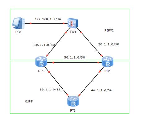
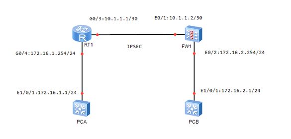
The topology is as shown in the figure ↓
Equipment model
FW1:DCFW-1800 Version 4.5
PCA:DCRS-5650 Version 7.0.3.1
PCB:DCRS-5650 Version 7.0.3.1
RT1:DCR-2655 Version 0.4.2
Configure IP and routing
DCRS-5650 analog PCA
DCRS-5650-28(R4)(config)#hostname PCA PCA(config)#vlan 233 PCA(config-vlan233)#int vlan 233 PCA(config-if-vlan233)#ip add 172.16.1.1 255.255.255.0 PCA(config-if-vlan233)#exit PCA(config)#interface ethernet 1/0/1 PCA(config-if-ethernet1/0/1)#switchport access vlan 233 Set the port Ethernet1/0/1 access vlan 233 successfully PCA(config-if-ethernet1/0/1)#exit PCA(config)#ip route 0.0.0.0 0.0.0.0 172.16.1.254
RT1
Router_config#hostname RT1 RT1_config#interface gigaEthernet 0/4 RT1_config_g0/4#ip address 172.16.1.254 255.255.255.0 RT1_config_g0/4#interface gigaEthernet 0/3 RT1_config_g0/3#ip address 10.1.1.1 255.255.255.252 RT1_config_g0/3#exit RT1_config#ip route 0.0.0.0 0.0.0.0 10.1.1.2
FW1
DCFW-1800(config)# hostname FW1 FW1(config)# interface ethernet0/1 FW1(config-if-eth0/1)# zone untrust FW1(config-if-eth0/1)# manage http FW1(config-if-eth0/1)# manage ping FW1(config-if-eth0/1)# manage telnet FW1(config-if-eth0/1)# ip address 10.1.1.2 255.255.255.252 FW1(config-if-eth0/1)# exit FW1(config)# interface ethernet0/2 FW1(config-if-eth0/2)# zone trust FW1(config-if-eth0/2)# manage http FW1(config-if-eth0/2)# manage ping FW1(config-if-eth0/2)# manage telnet FW1(config-if-eth0/2)# ip address 172.16.2.254 255.255.255.0 FW1(config-if-eth0/2)# exit FW1(config)# ip vrouter trust-vr FW1(config-vrouter)# ip route 0.0.0.0 0.0.0.0 10.1.1.1 FW1(config-vrouter)# exit
DCRS-5650 analog PCB
DCRS-5650-28(R4)(config)#hostname PCB PCB(config)#vlan 233 PCB(config-vlan233)#int vlan 233 PCB(config-if-vlan233)#ip address 172.16.2.1 255.255.255.0 PCB(config-if-vlan233)#exit PCB(config)#interface ethernet 1/0/1 PCB(config-if-ethernet1/0/1)#switchport access vlan 233 PCB(config-if-ethernet1/0/1)#exit PCB(config)#ip route 0.0.0.0 0.0.0.0 172.16.2.254
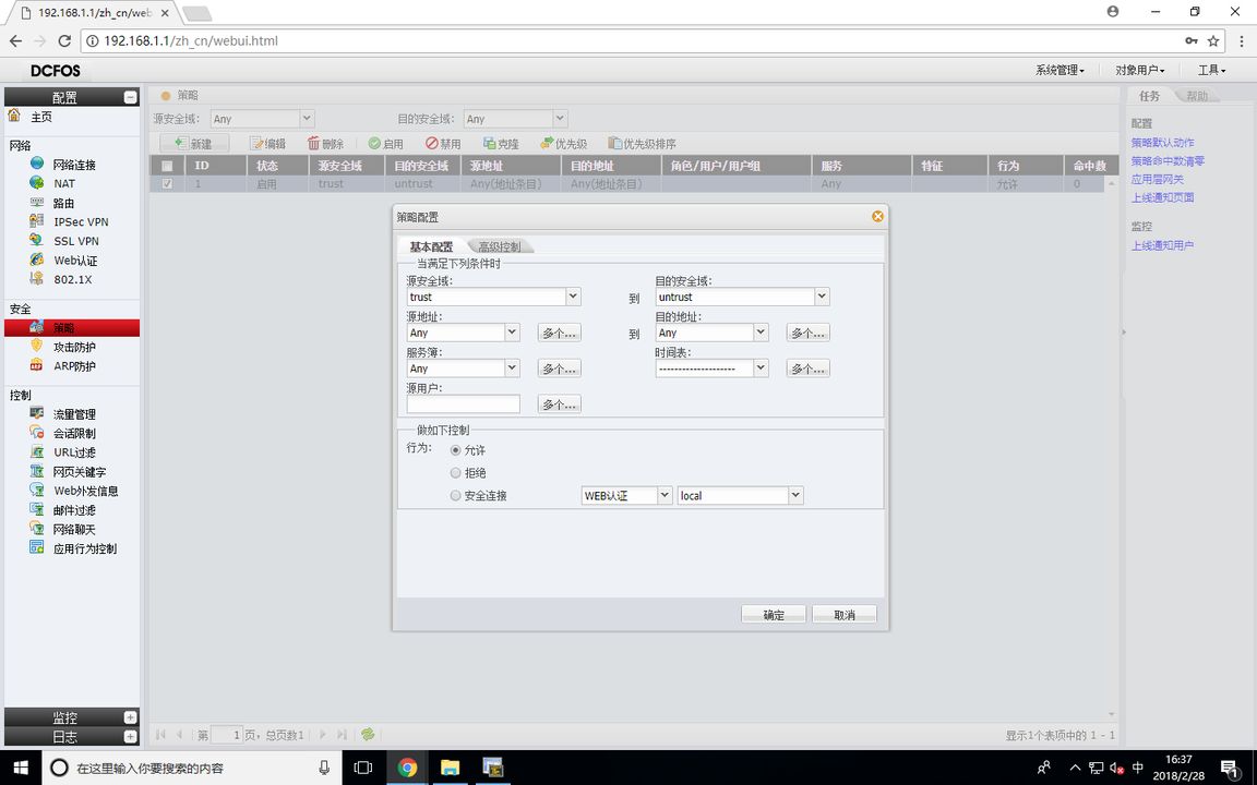
FW1 Configuration Policy
test
PCB#ping 172.16.1.1 Type ^c to abort. Sending 5 56-byte ICMP Echos to 172.16.1.1, timeout is 2 seconds. !!!!! Success rate is 100 percent (5/5), round-trip min/avg/max = 0/6/33 ms PCA#ping 172.16.2.1 Type ^c to abort. Sending 5 56-byte ICMP Echos to 172.16.2.1, timeout is 2 seconds. ..... Success rate is 0 percent (0/5), round-trip min/avg/max = 0/0/0 ms
At this time, the PCB can ping the PCA, but the PCA cannot ping the PCB, because now the firewall only allows the data stream from Trust to Untrust to pass through, and the firewall default setting rejects all data streams to pass through
Configure IPSEC VPN
RT1
RT1_config#ip access-list extended 1 RT1_config_ext_nacl#permit ip 172.16.1.0 255.255.255.0 172.16.2.0 255.255.255.0 // Match the data flow for IPSEC VPN RT1_config_ext_nacl#exit RT1_config # crypto isakmp policy 1//Set the IKE encryption policy. The configuration must be consistent with the firewall P1 proposal RT1_config_isakmp # group 2//DH group RT1_config_isakmp # authentication pre share//Set the encryption mode: shared key RT1_config_isakmp # hash md5//Verification algorithm RT1_config_isakmp # encryption 3des//Encryption algorithm RT1_config_isakmp#exit RT1_config # crypto isakmp key 123456789 10.1.1.2//Set the shared key RT1_config # crypto ipsec transform set 1//Set the tunnel encryption algorithm. The configuration must be consistent with the firewall P2 proposal RT1_config_crypto_trans # mode tunnel//Set to tunnel mode RT1_config_crypto_trans # transform type esp-3des esp-md5-hmac//Set 3des encryption, md5 verification RT1_config_crypto_trans#exit RT1_config # crypto map 1 10 ipsec isakmp//Set the encryption mapping table RT1_config_crypto_map # match address 1//Bind ACL RT1_config_crypto_map # set peer 10.1.1.2//Set VPN peer address RT1_config_crypto_map # set transform set 1//Bind the exchange set RT1_config_crypto_map#exit RT1_config#interface gigaEthernet 0/3 RT1_config_g0/3 # crypto map 1//Apply encryption mapping table RT1_config_g0/3#exit
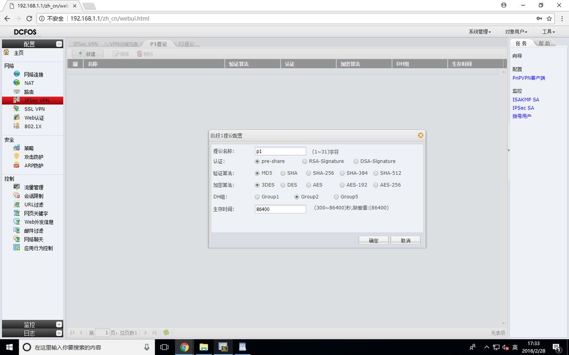
FW1 (P1 proposal)
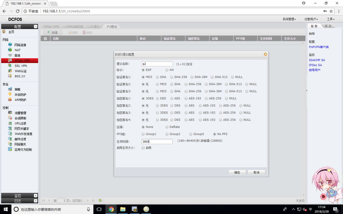
FW1 (P2 proposal)
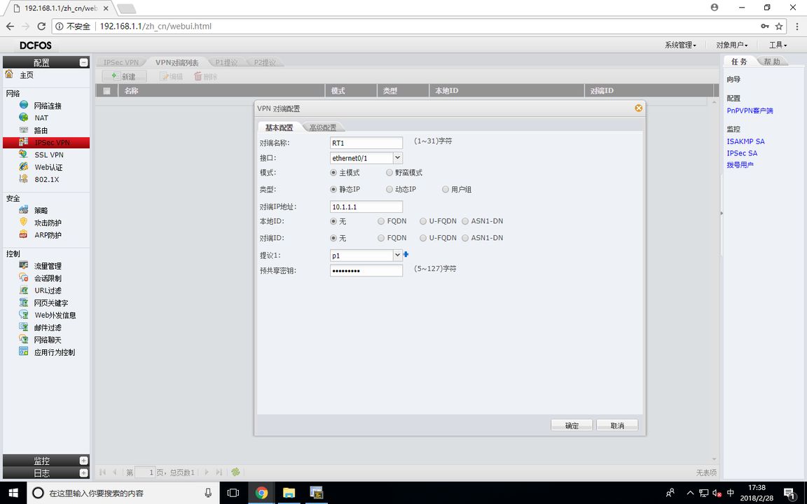
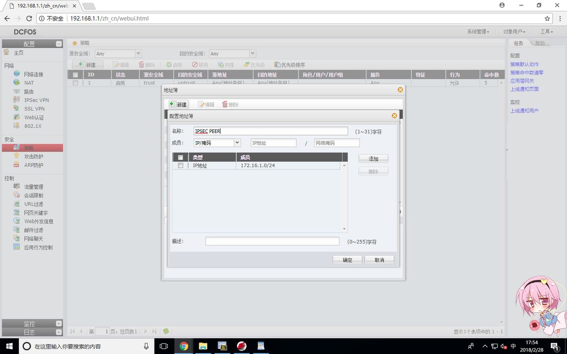
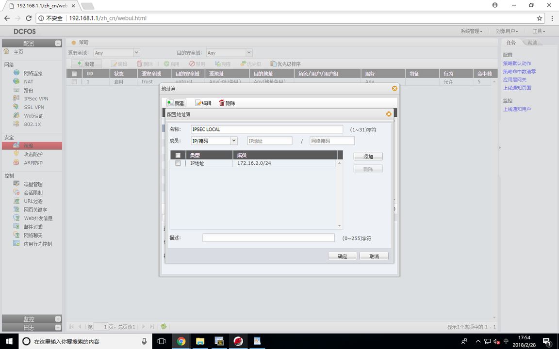
FW1 (VPN peer list)
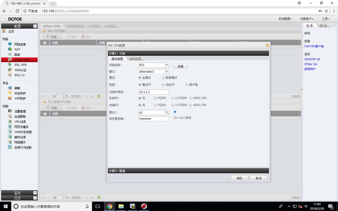
FW1 (IKE VPN configuration)
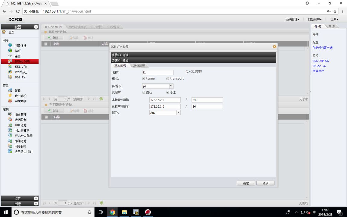
FW1 (tunnel encryption configuration)
The proxy is the data stream to be encrypted, and the router matches the encrypted data stream for ACL
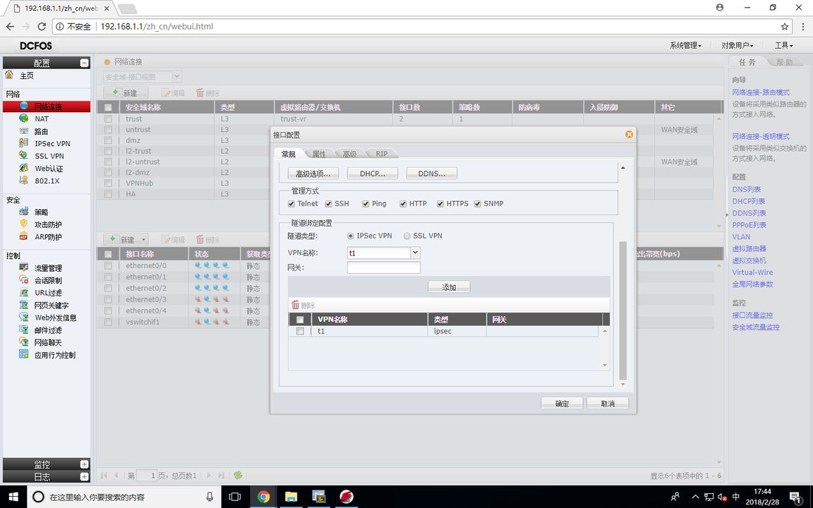
FW1 (Tunnel Binding Configuration)
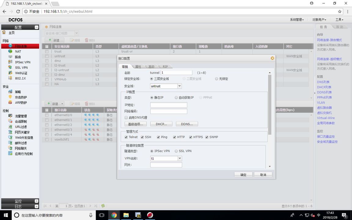
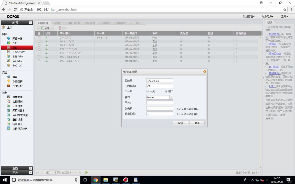
Since the firewall cannot configure the encryption mapping table on E0/1, it can only be bound with the tunnel interface, so the next hop of a route to 172.16.1.0/24 should be directed to the tunnel interface, so that it can encrypt the IPSEC VPN
FW1 (static route to configure )
FW1 (VPN address pool configuration )
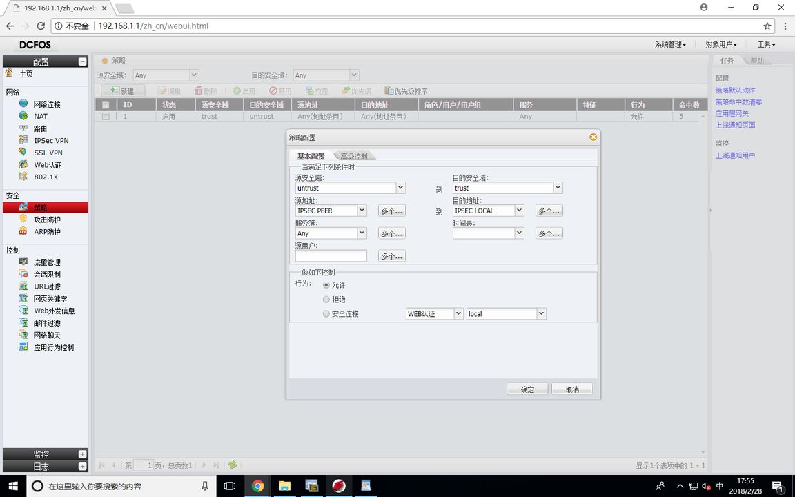
FW1 (VPN policy configuration )
test
PCB#ping 172.16.1.1 Type ^c to abort. Sending 5 56-byte ICMP Echos to 172.16.1.1, timeout is 2 seconds. .!!!! Success rate is 80 percent (4/5), round-trip min/avg/max = 0/0/0 ms PCA#ping 172.16.2.1 Type ^c to abort. Sending 5 56-byte ICMP Echos to 172.16.2.1, timeout is 2 seconds. !!!!! Success rate is 100 percent (5/5), round-trip min/avg/max = 0/0/0 ms
View IPSEC SA
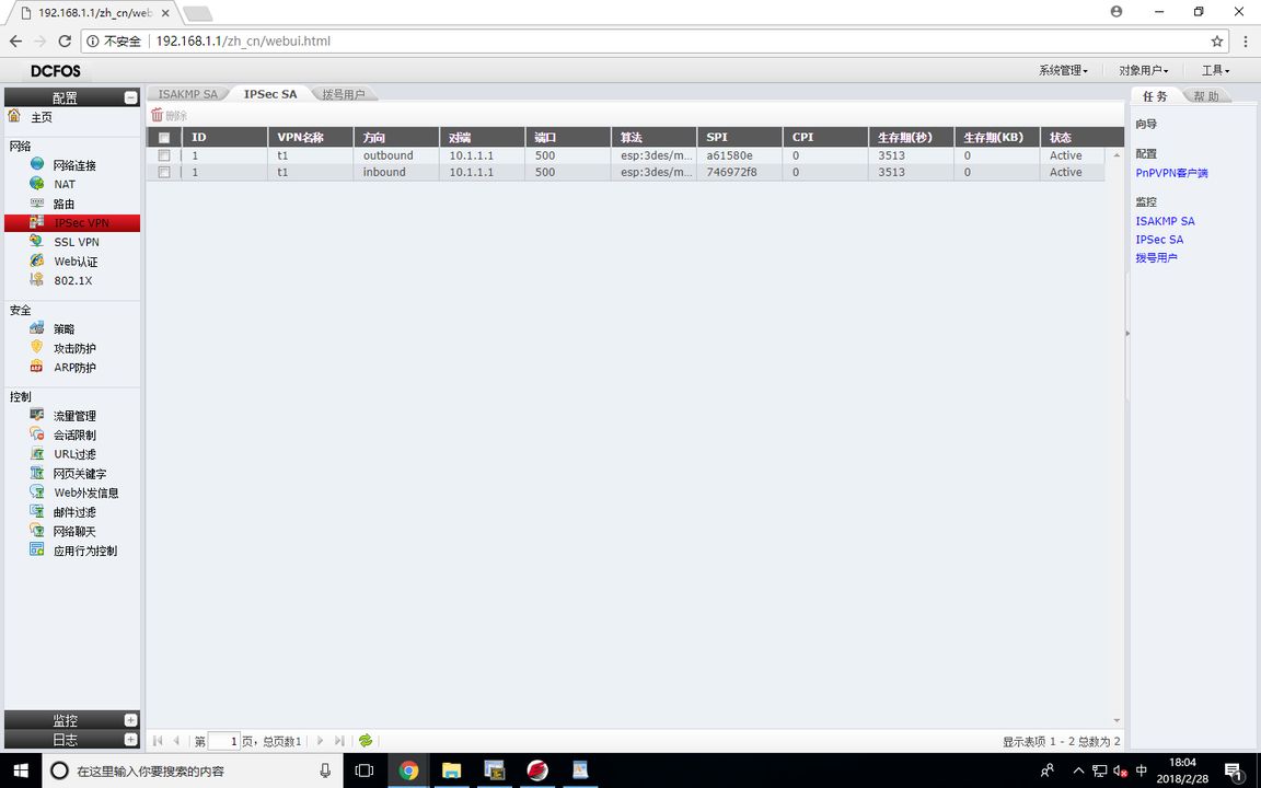
RT1#show crypto ipsec sa Interface: GigaEthernet0/3 Crypto map name:1 , local addr. 10.1.1.1 local ident (addr/mask/prot/port): (172.16.1.0/255.255.255.0/0/0) remote ident (addr/mask/prot/port): (172.16.2.0/255.255.255.0/0/0) local crypto endpt.: 10.1.1.1, remote crypto endpt.: 10.1.1.2 inbound esp sas: spi:0xa61580e(174151694) transform: esp-3des esp-md5-hmac in use settings ={ Tunnel } sa timing: remaining key lifetime (k/sec): (4607999/3443) outbound esp sas: spi:0x746972f8(1953067768) transform: esp-3des esp-md5-hmac in use settings ={ Tunnel } sa timing: remaining key lifetime (k/sec): (4607999/3443)
View ISAKMP SA
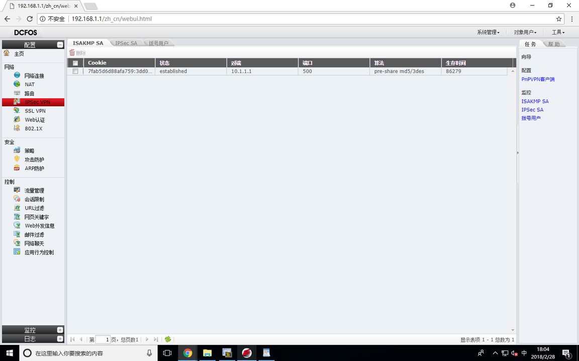
RT1#show crypto isakmp sa dst src state state-id conn 10.1.1.2 10.1.1.1 <R>Q_SA_SETUP 3 6 1 10 10.1.1.2 10.1.1.1 <R>M_SA_SETUP 2 6 1 10