CATIA is a machining design software created by Dassault. CATIA software has a wide range of applications and powerful functions. It can not only provide you with practical design solutions, but also provide accurate 2D, 3D, parametric hybrid modeling and data management means.It will bring you an efficient and convenient use experience.If you need this tool, please download it.
Introduction to CATIA Software Features
1. Reconstructed next-generation architecture
2. Support scalability of different application levels
3. Independence from NT and UNIX hardware platforms
4. Capture and reuse of specialized knowledge
5. Smooth upgrade for existing customers
What's New in CATIA Software
1. ALoft command enhancement
2. Sketcher enhancements
3. 2D format enhancement
4. Flexibility enhancement
5. Enhance harness leveling ergonomic design and firmness
6. Enhanced machining simulation
7. Increase openness
8. Transition to Version 6
CATIA installation steps
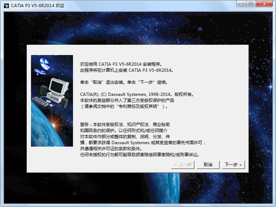
1. First, you need to download the CATIA software package on this site. After the download is completed, you will get a compressed package. We can right click and select decompression. After decompression, we can double-click the "setup. exe" file to start the installation, as shown in the following figure, we can click Next to continue the installation.
2. Enter the CATIA installation location selection interface, as shown in the figure below, you can directly click Next, and the software will be installed in the system disk C by default. However, I suggest you choose to define the installation spontaneously. Disk C is the system disk, and too much software memory will cause the computer to run slowly.
3. You can click Browse in the interface to select custom installation. After clicking Browse, you can choose the installation location by yourself. After we select other locations, click Next at the bottom of the interface to install.
4. Enter the CATIA software installation type selection interface.As shown in the figure below, you can choose full installation or custom installation. However, Xiaobian recommends that users choose full installation to ensure the integrity of the software.
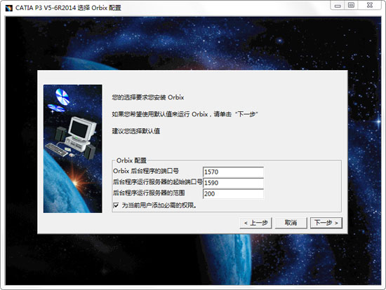
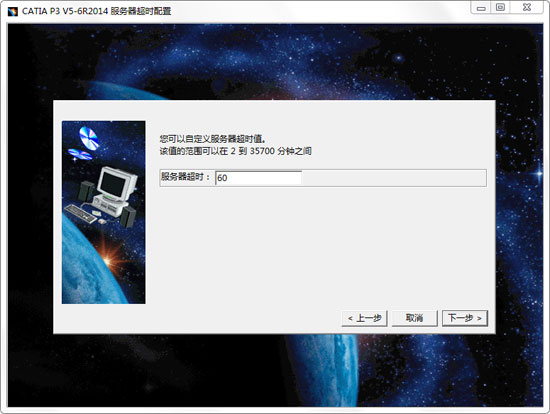
4. Next, we enter the interface in the figure below of CATIA software. We need to install orbix and configure orbix at the bottom of the interface. If you do not set it here, you can select the default value without making any changes.
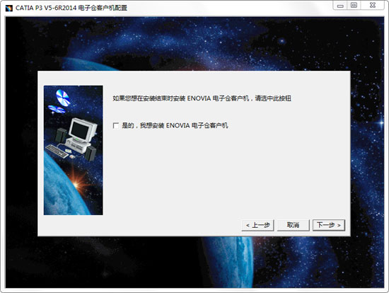
5. Enter the software installation preparation interface, as shown in the figure below. We check the option I want to install, and then click Next at the bottom of the interface.
6. The CATIA software is being installed, as shown in the figure below. You need to wait patiently for the installation to complete. Because the software is relatively large, the installation still needs some time. We can just wait patiently.
7. The CATIA software is installed, as shown in the figure below, we can check the "I want to start now" option, and then click the "Finish" option at the bottom of the interface to close the installation interface and open the software for use.
CATIA FAQs
1、 How does catia v5 carry out assembly design and assemble parts?
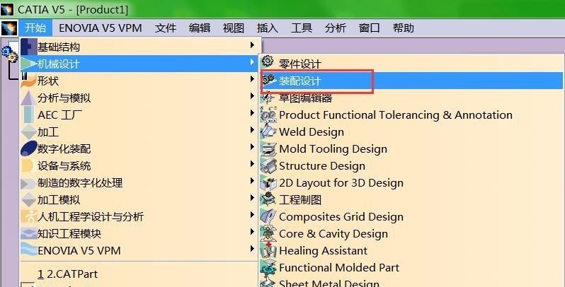
1. First, we open and download the catia v5 software, and then we enter the main interface of the software, as shown in the figure below. We click the "Start" option at the top of the interface, and then click the mechanical design option in the pull-down menu bar. Next, a menu bar will appear on the right side of the option. We click the "Assembly Settings" option to enter the assembly design interface.
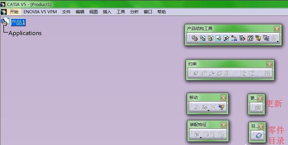
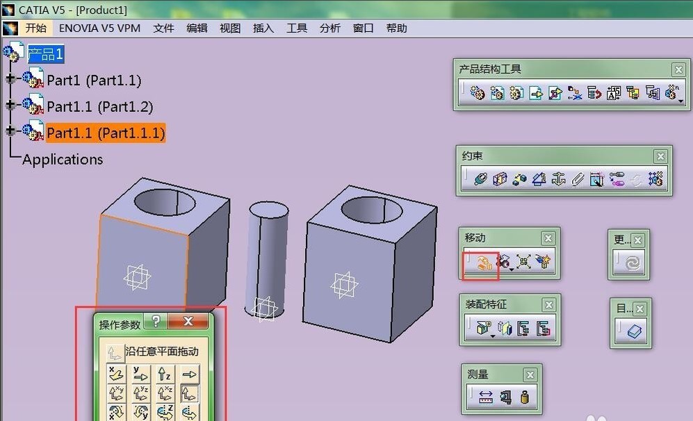
2. We enter the assembly design interface, as shown in the figure below, where there will be toolbars of Product Structure Tool, Constraint, Move, Assembly Feature, Measure, Update, and Part Catalog.
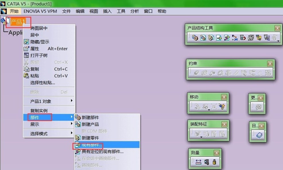
3. Next, we import the components. We click the "Product I" option in the following figure, then find the "Assembly" option in the drop-down menu bar and click it. Then the drop-down option appears on the right side of the option, and we click the "Existing Assembly" option to import components or parts.
4. Next, we start to move the parts. We click the "Operation" option in the moving toolbar in the interface, and Jessie can open the selection box of the operating parameters, as shown in the figure below. There are many moving methods, and we can select one suitable one.
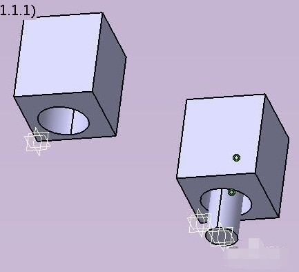
5. Next, we will constrain the components. In the constraint menu bar in the interface below, as shown in the following figure, we can set the components through the constraint toolbar.As shown in the figure below, we can click the [Coincidence] option in the constraint toolbar, and then click [Update] to find that the axis of the cylinder and the cylinder groove coincide.
6. Next, we can also use the options in the assembly feature toolbar. You can click the Symmetry button in the toolbar to achieve symmetry.
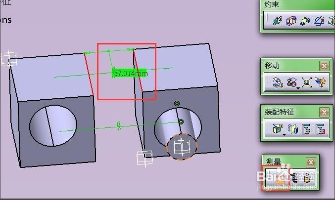
7. You can use the measurement option in the assembly feature toolbar, as shown in the following figure. Click the measurement option to measure the distance and angle between lines and planes, which is convenient for comparison.
8. Finally, we can also use the catalog toolbar. There are bolt, nut and other part models under the catalog toolbar. You can select appropriate ones according to your needs and import them directly, which is simple and practical.
2、 How does catia v5 draw gears?
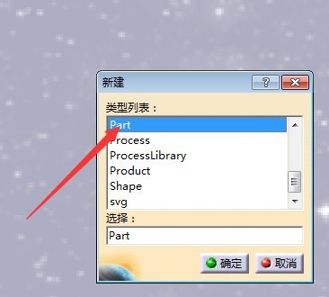
1. First, we open the catia v5 software to enter the main interface, then we use the shortcut key Ctrl+N to enter the new interface, as shown in the figure below, we select PART to enter the part design interface;
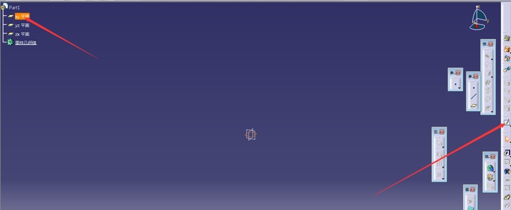
2. Enter the interface in the following figure, we can see that there is an option of xy plane, and we click the sketch.
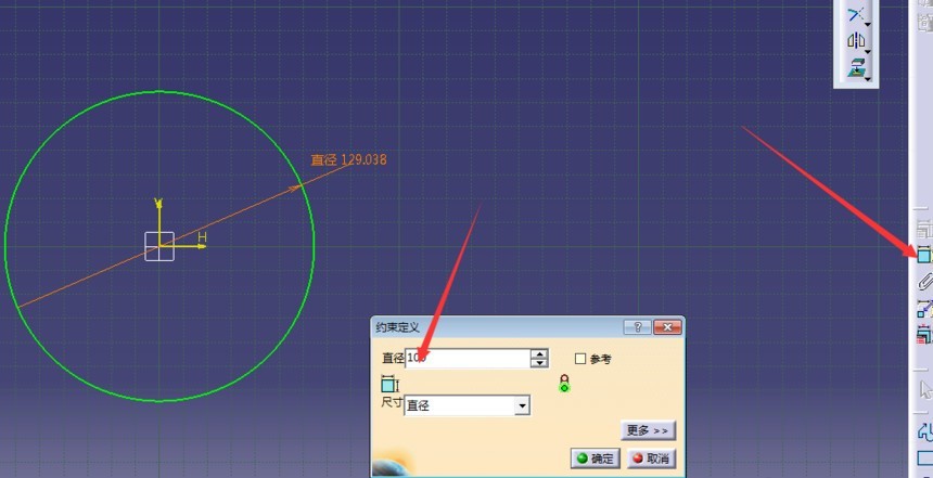
3. As shown in the figure below, we enter the constraint definition interface, where you can set the diameter and size of the circle drawn in the selected plane. After we finish setting, click OK.You can follow the steps in the following figure.
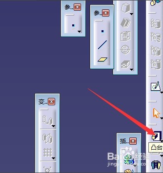
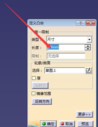
4. We click the boss option on the right side of the software interface to enter the definition boss interface in the following figure. We can set information such as type and length. It is recommended to use the default length, and then click OK.
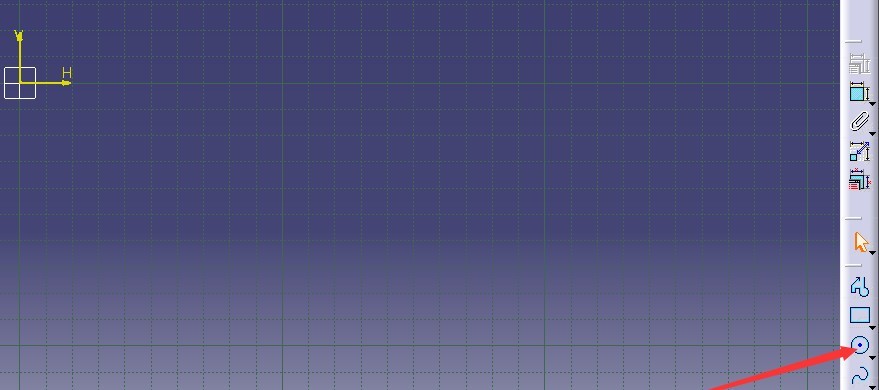
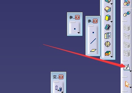
5. Next, we click the plane option on the right side of the interface to enter the sketch interface and start to draw the required gear;
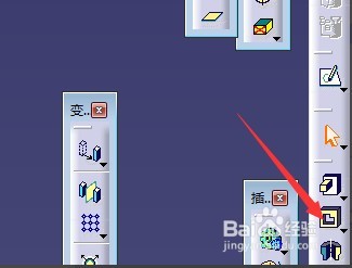
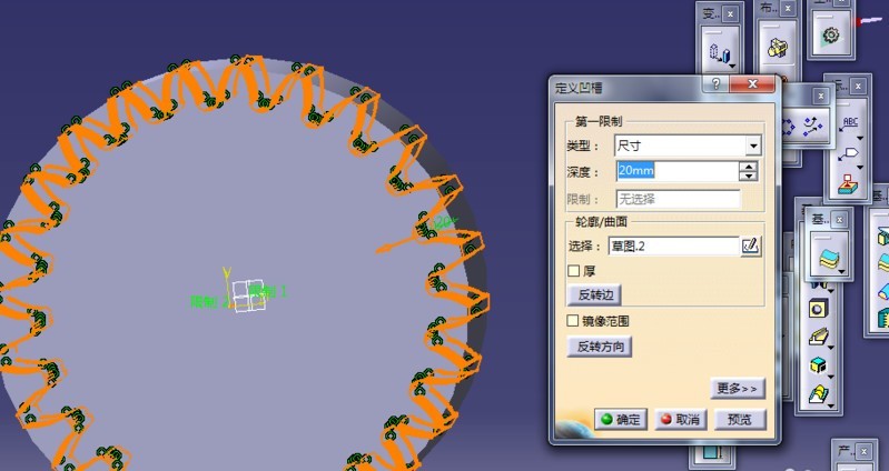
6. As shown in the figure below, we follow the steps in the figure to exit the workbench, click the groove option on the right, set the default size, and then proceed to the next step.
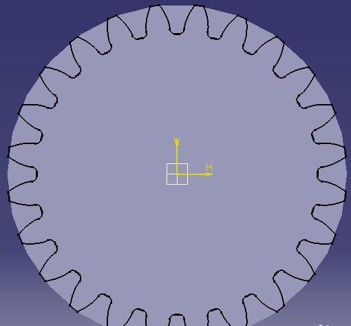
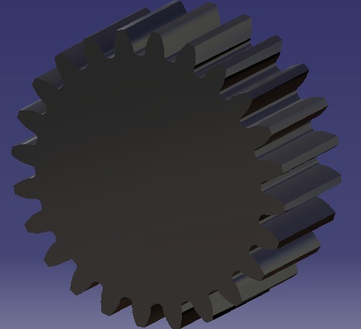
7. We need to check the reverse edge option in the interface for defining grooves in the previous step. After selecting it, we can save the settings and add materials, as shown in the following figure. After the settings are completed, we can successfully draw gears.
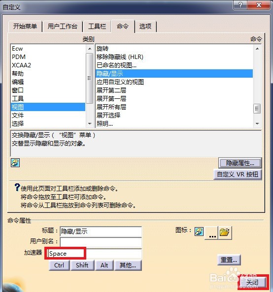
3、 How to set shortcut keys in CATIA V5?
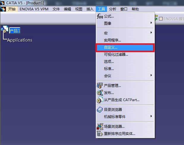
1. Open Catia software to enter the main interface. We find the "Tools" option at the top of the interface, and then click "Customize" in the lower menu bar, and then proceed to the next step.
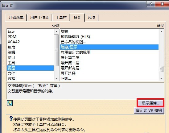
2. We enter the custom interface, we click it without pressing the command option above, then find the "View" option in the window on the left side of the interface and click it, and then clean the window on the right side, we can see the "Hide and Show" option. We click it, select it, and then click the "Display Properties" option at the bottom of the interface to proceed to the next step.
3. After we click "Display Properties", as shown in the figure below, we can see the command properties at the bottom of the interface. We enter "Space" in the content editing box, and click the "Close" button.This completes the shortcut key settings.
Tip: Your comments are of great reference value to other users. Please do not enter comments without nutrition. If you encounter problems, please report them so that we can deal with them in a timely manner.