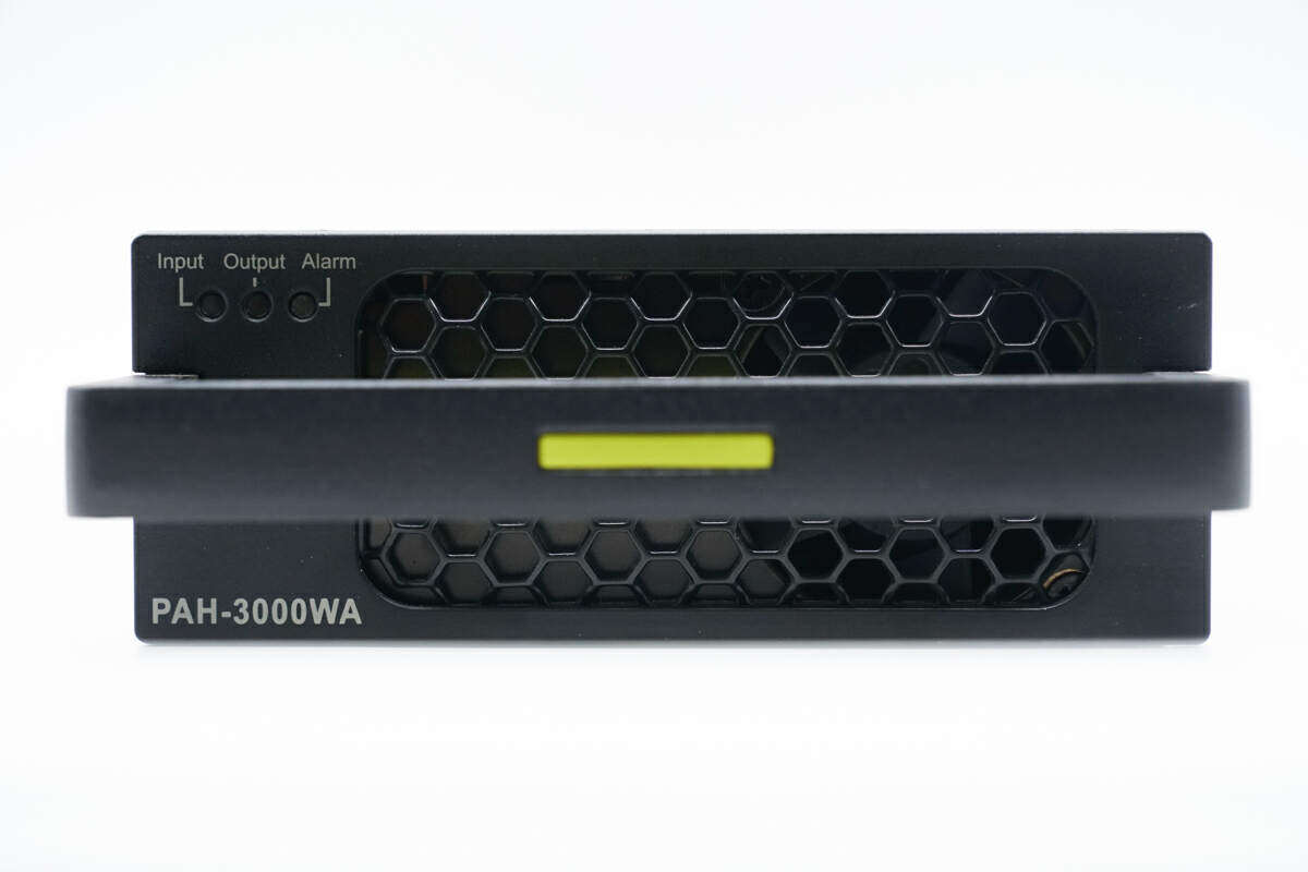
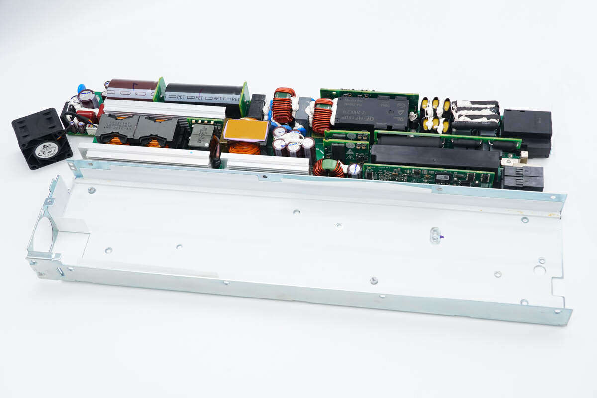
The charging head has been found onlineHuaweiCloudEngine 16800 Series Switch Power Module PAH-3000WA. This power supply is designed as a redundant power supply with a strip shape and metal shell.The front end of the power module is provided with a cooling fan and a handle, and the output end is provided with a connector.This module has no external power cord. The input, output and communication pins are all connected through the gold finger at the tail, which is clean and tidy.
The power module has3000WOutput power, supporting AC and DC input.The power output specification is 53.5V 56.1A, and the calculated output power is3000WAnd supports the corresponding reduction of output power according to the reduction of input voltage. Under the 110Vac input, the output power is derated to 1500W.Here comes PAH-3000WA Take a look at the internal materials and design of the disassembly of the power module.
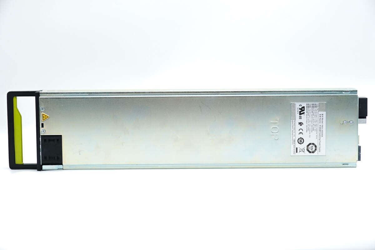
HuaweiThe 3000W switching power supply PAH-3000WA adopts a metal shell, which is sealed and fixed with screws in the classic splicing mode, and has positioning slideways on both sides.The first impression of the power supply is that it is very long and important.
The front shell of the switching power supply is sprayed with black paint, which is actually also made of metal, and there is a PAH-3000WA model at the lower left corner.
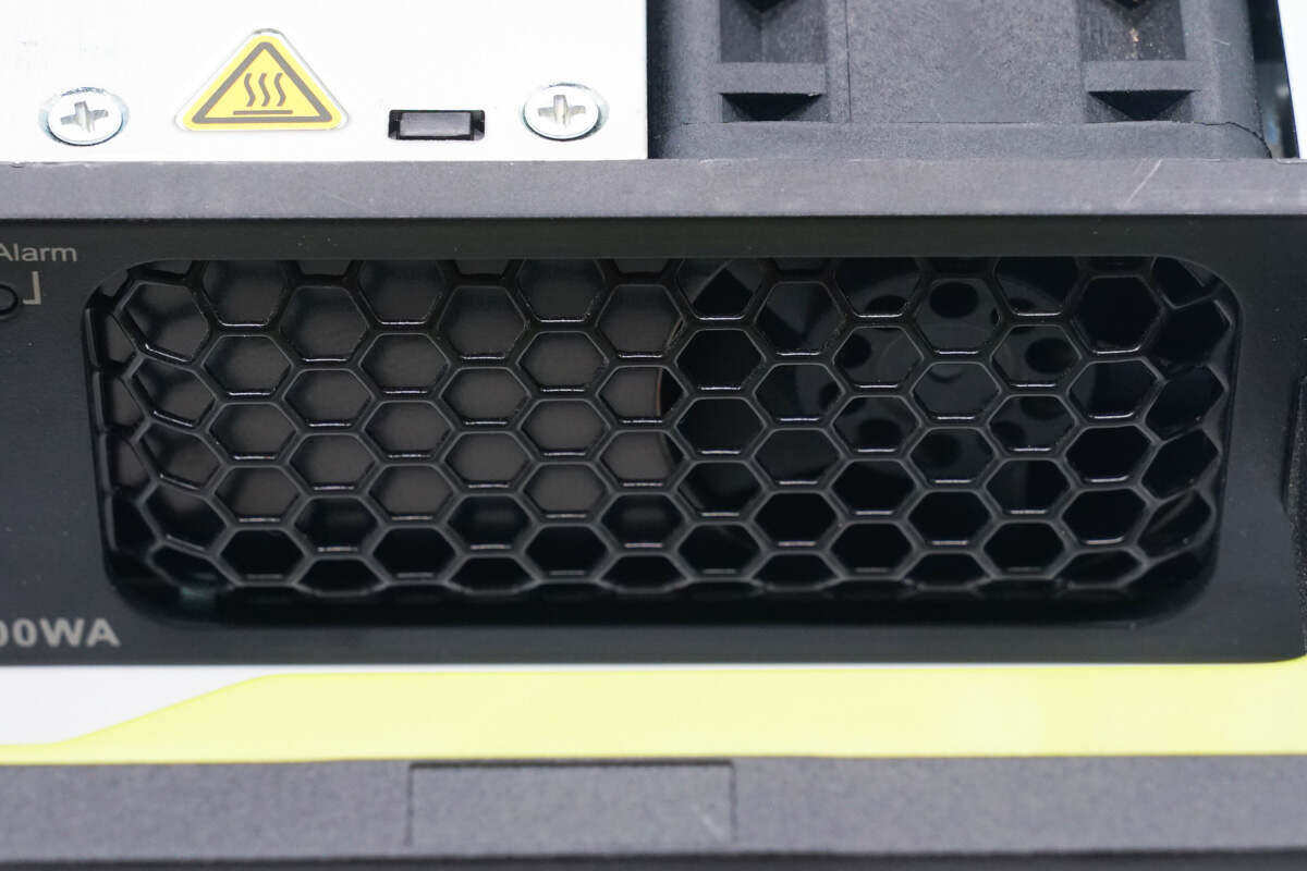
The front housing grille is designed for air circulation.
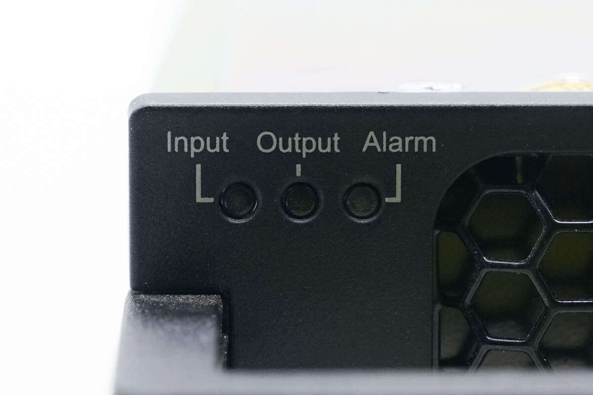
Input, output and warning indicators are set at the upper left corner.
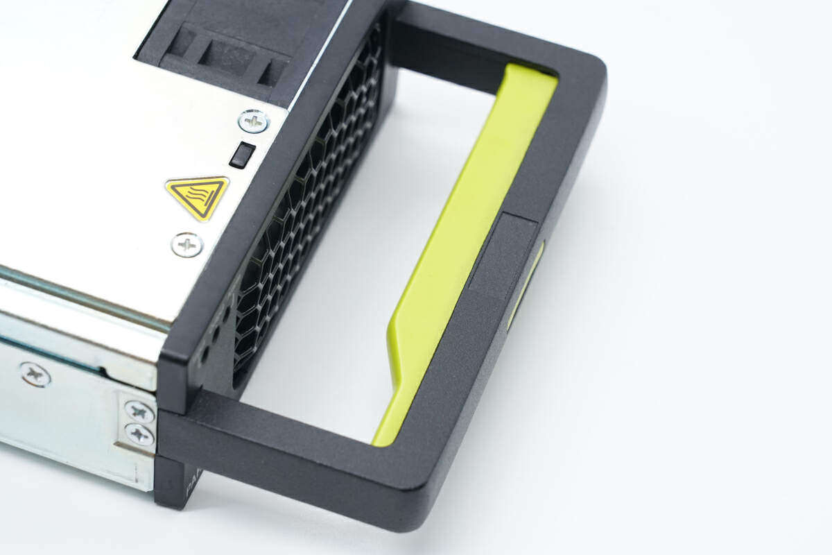
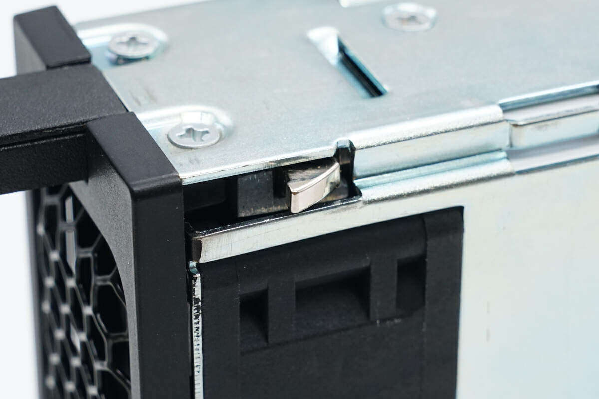
In addition, the front end is also provided with a plastic handle, and the inside of the handle is provided with a yellow green release button.
The side of the fuselage is equipped with a lock catch, which can be released by pressing the yellow green release buttonHuawei3000W switching power supply PAH-3000WA is taken out.
The nameplate of switching power supply is pasted on the top of the machine body, and the manufacturer information on the nameplate has been deliberately damaged.
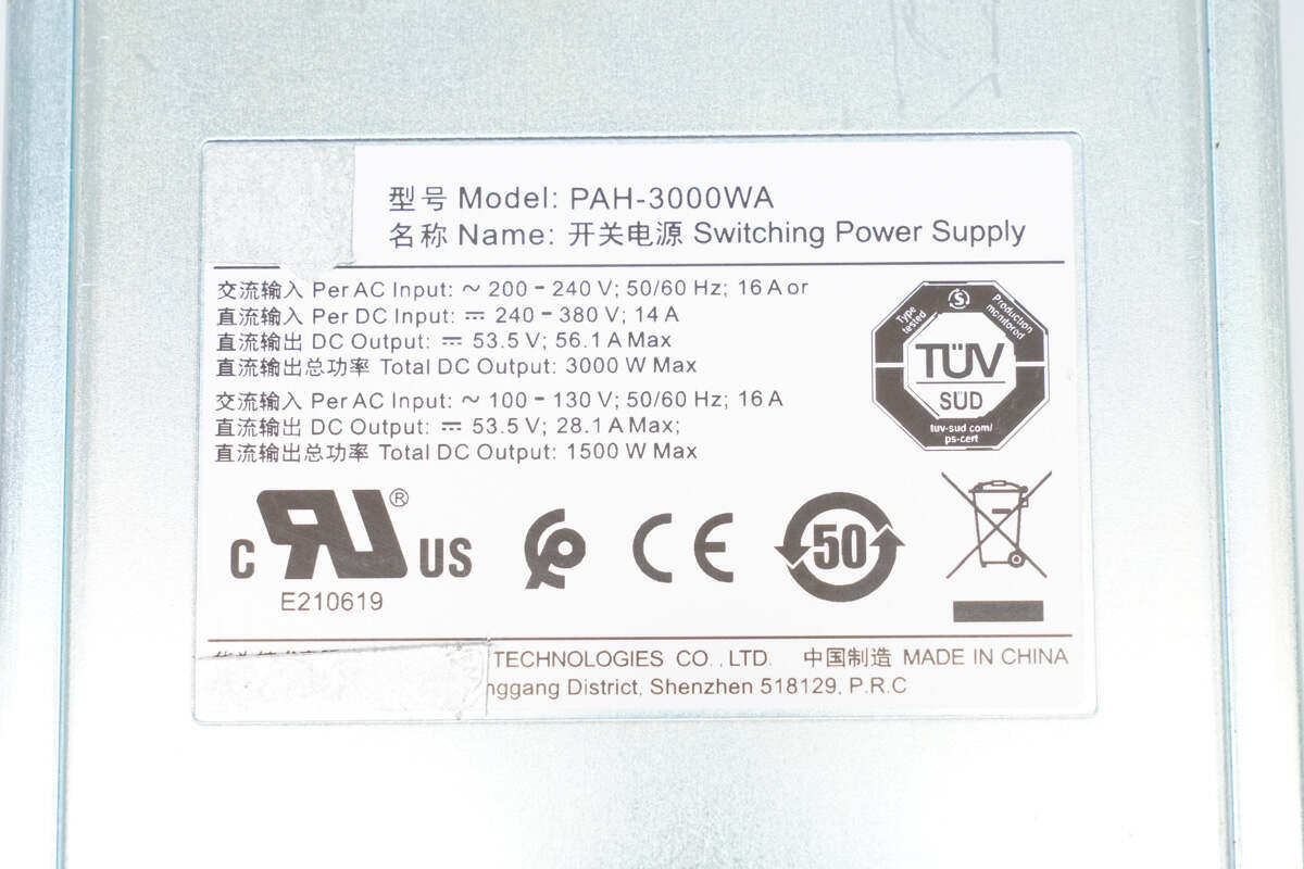
Close up of switch power supply nameplate
Model: PAH-3000WA
AC input:~200-240V;50/60Hz;16A or
DC input: 240-380V;14A
DC output: 53.5V;56.1A Max
Total DC output power: 3000W Max
AC input:~100-130V;50/60Hz;16A
DC output: 53.5V;28.1A Max
Total DC output power: 1500W Max
The switching power supply has passed the certification of CP, CE and TUV.
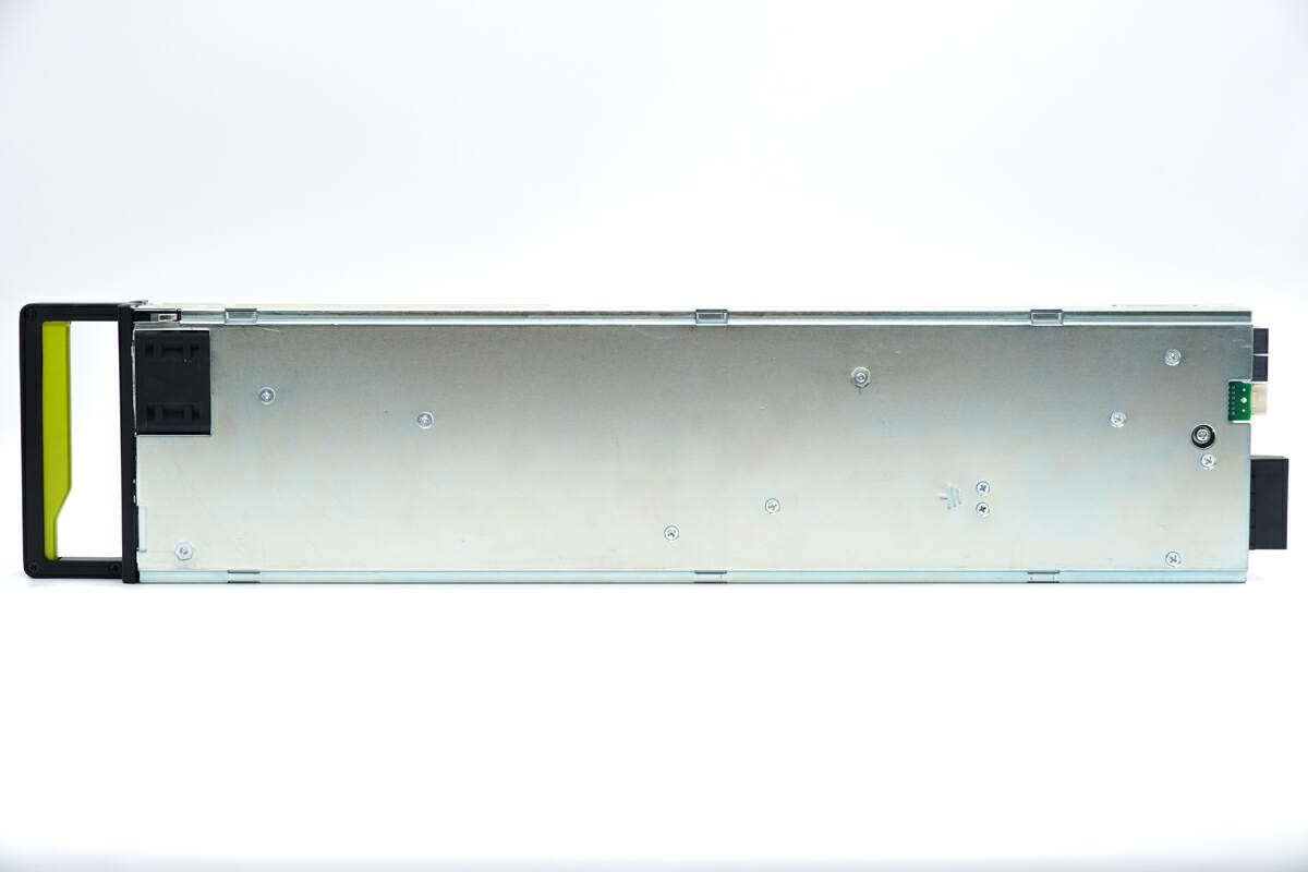
Both sides of the bottom of the fuselage are also provided with positioning slideways.
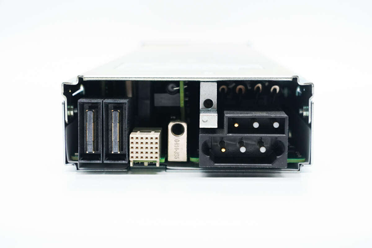
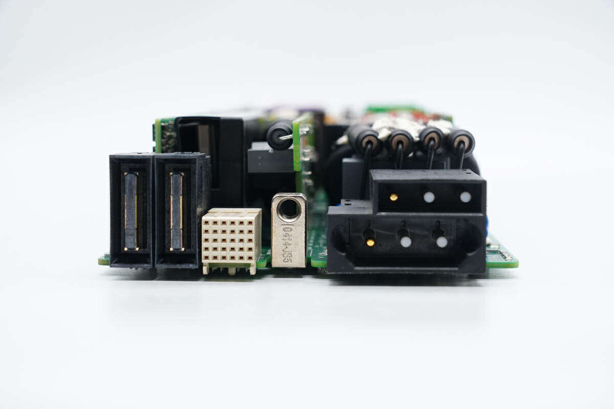
The switch power supply input and output bus bases are set at the same end. The left side is the DC output socket and power control socket, and the right side is the power input terminal, with a hierarchical structure from top to bottom.
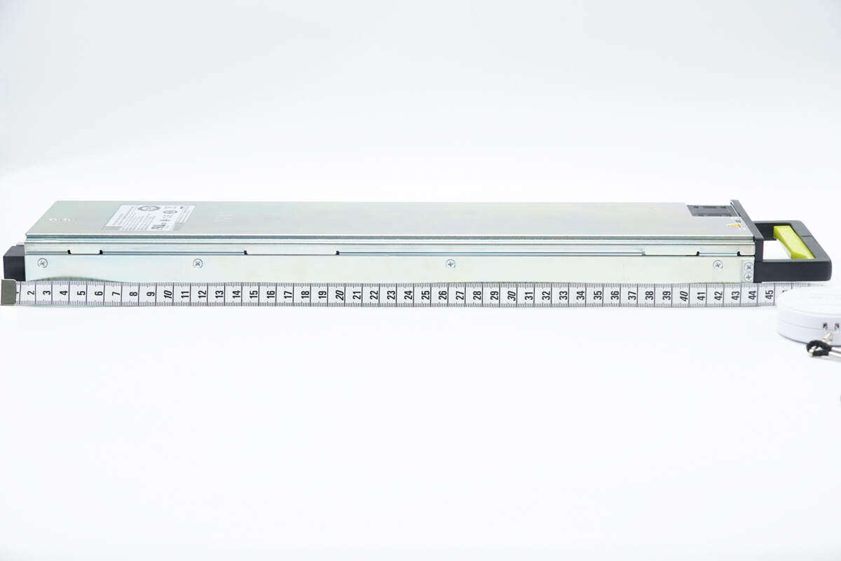
MeasuredHuawei3000W switching power supply PAH-3000WA body length is about 44cm.
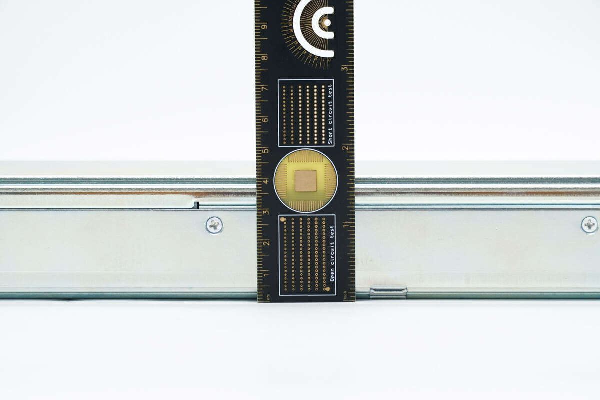
The body width is about 10.3cm.
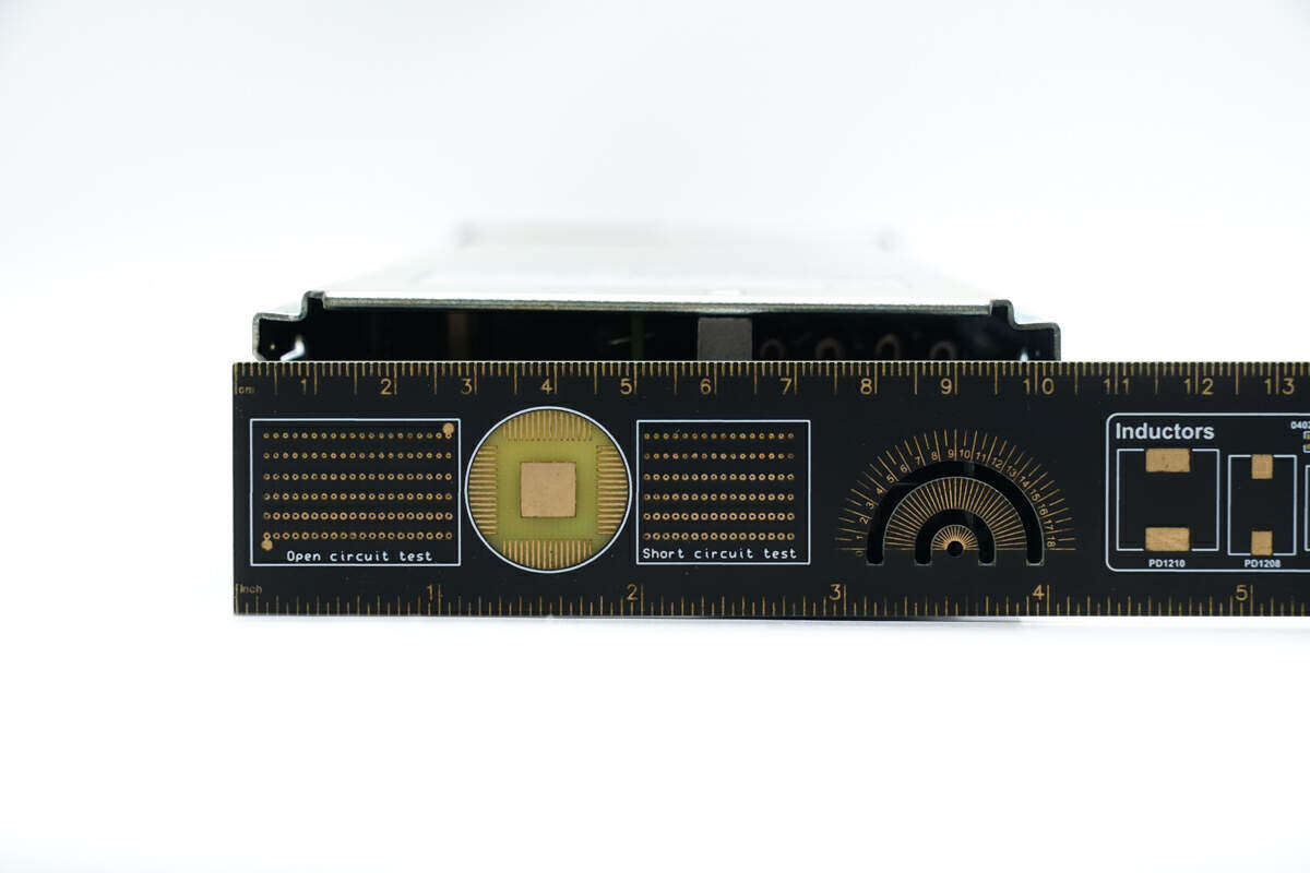
The thickness is about 4cm.
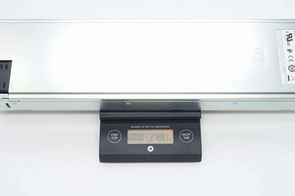
In addition, the measured weight of the power module is about 2788g.
Disassembly of Huawei 3000W power module PAH-3000WA
After seeing the appearance of Huawei's power module, let's disassemble it to see the internal materials and design.
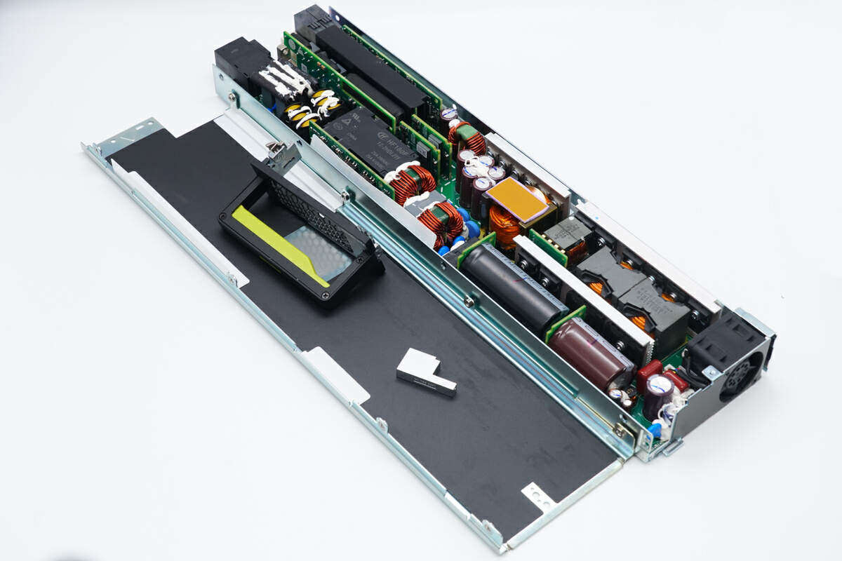
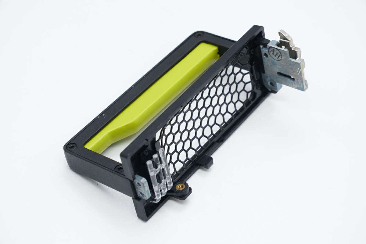
First, unscrew all the fixing screws on the metal housing and remove the power module panel and cover plate.
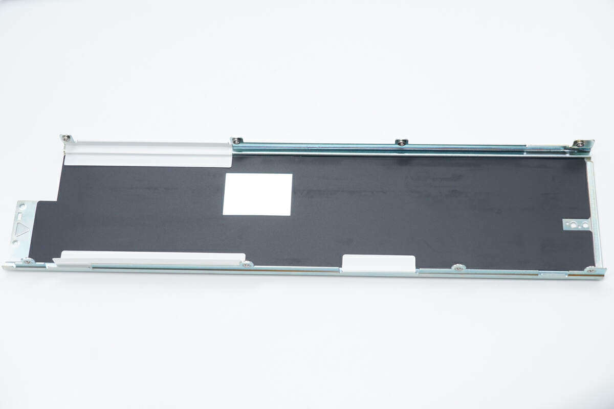
Black Mylar sheet insulation is pasted inside the cover plate.
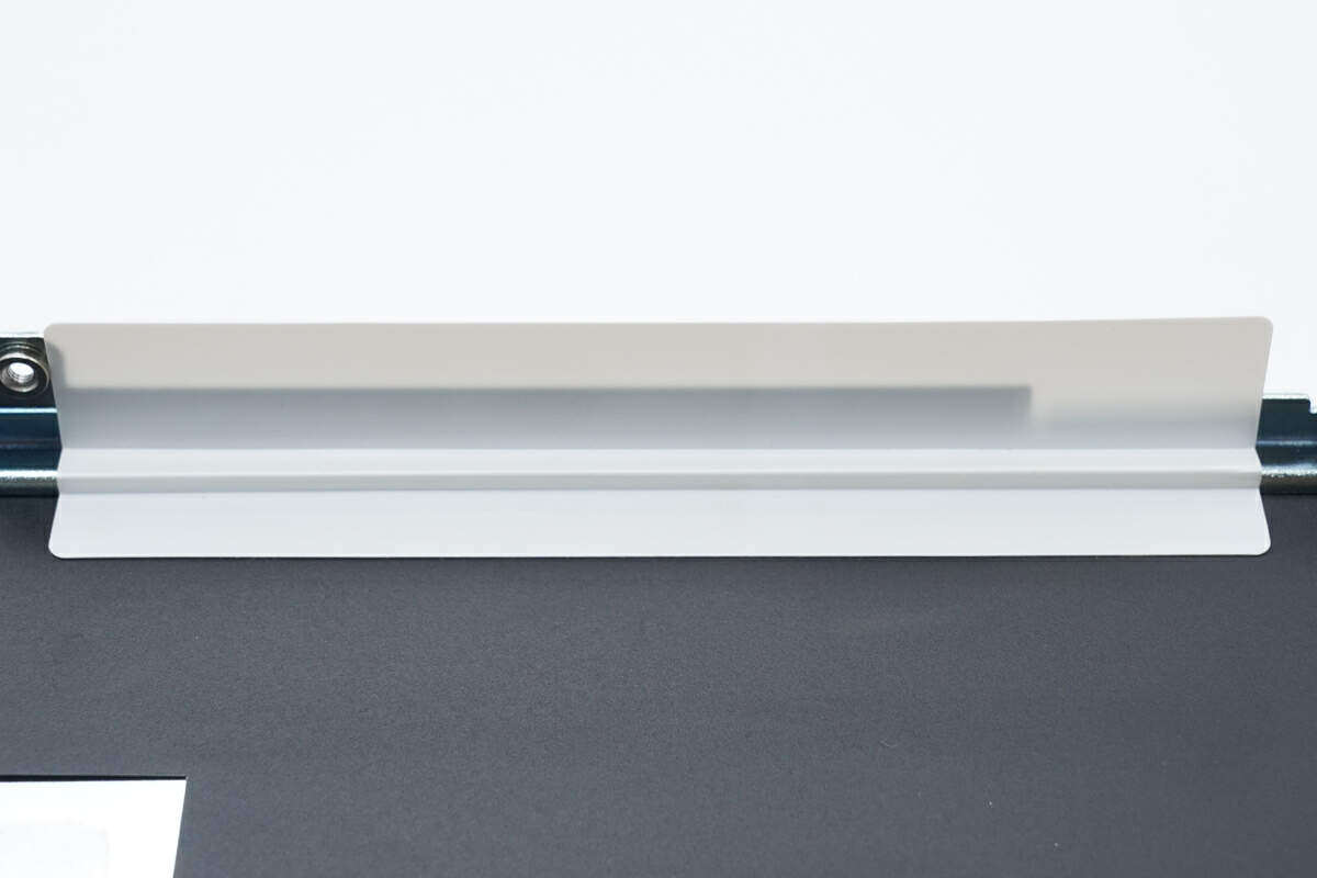
The side of the cover plate is also pasted with Mylar insulation.
Close up of the front handle structure of the power module, and the grille is used for air circulation.
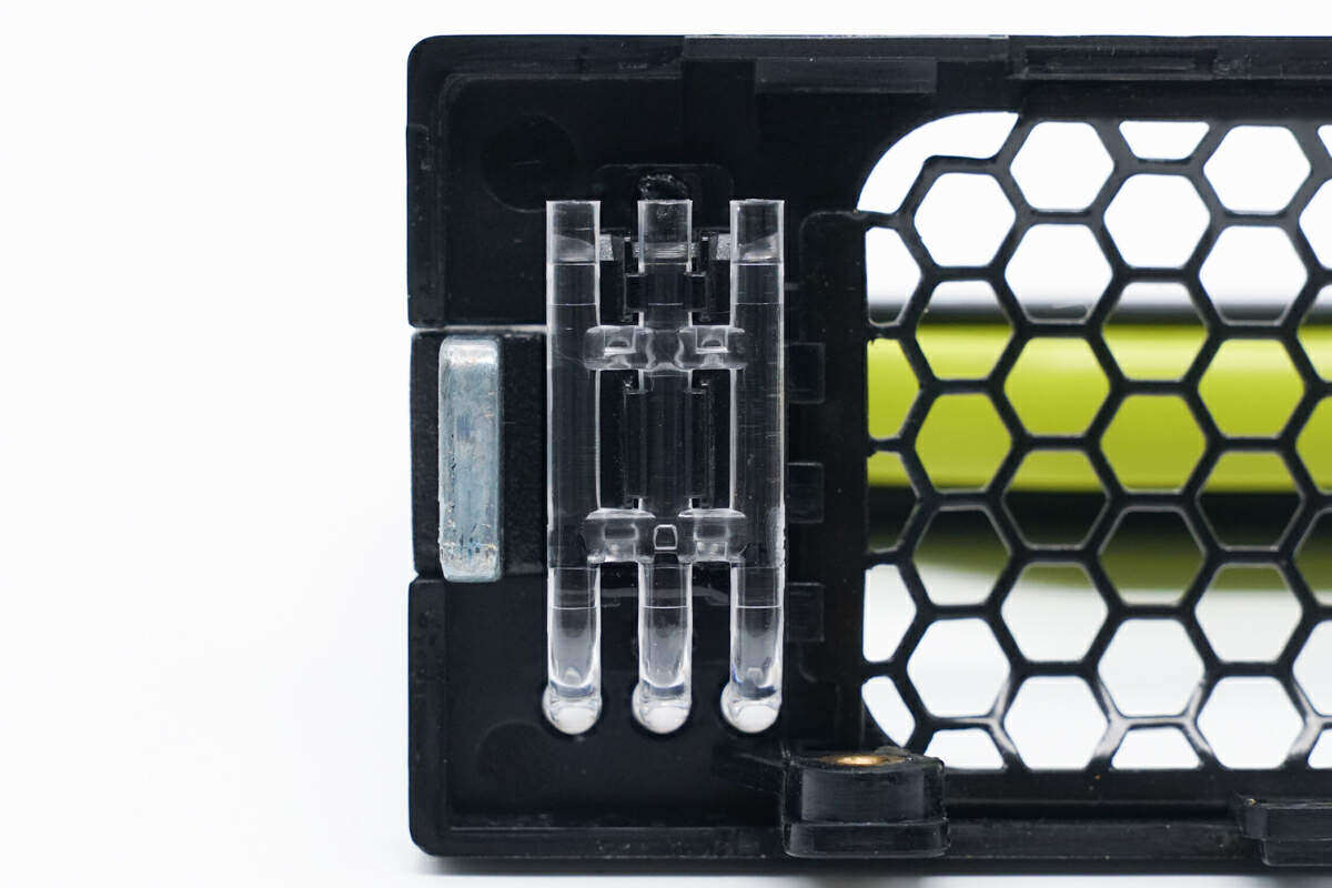
Close up of the light guide structure of the work indicator.
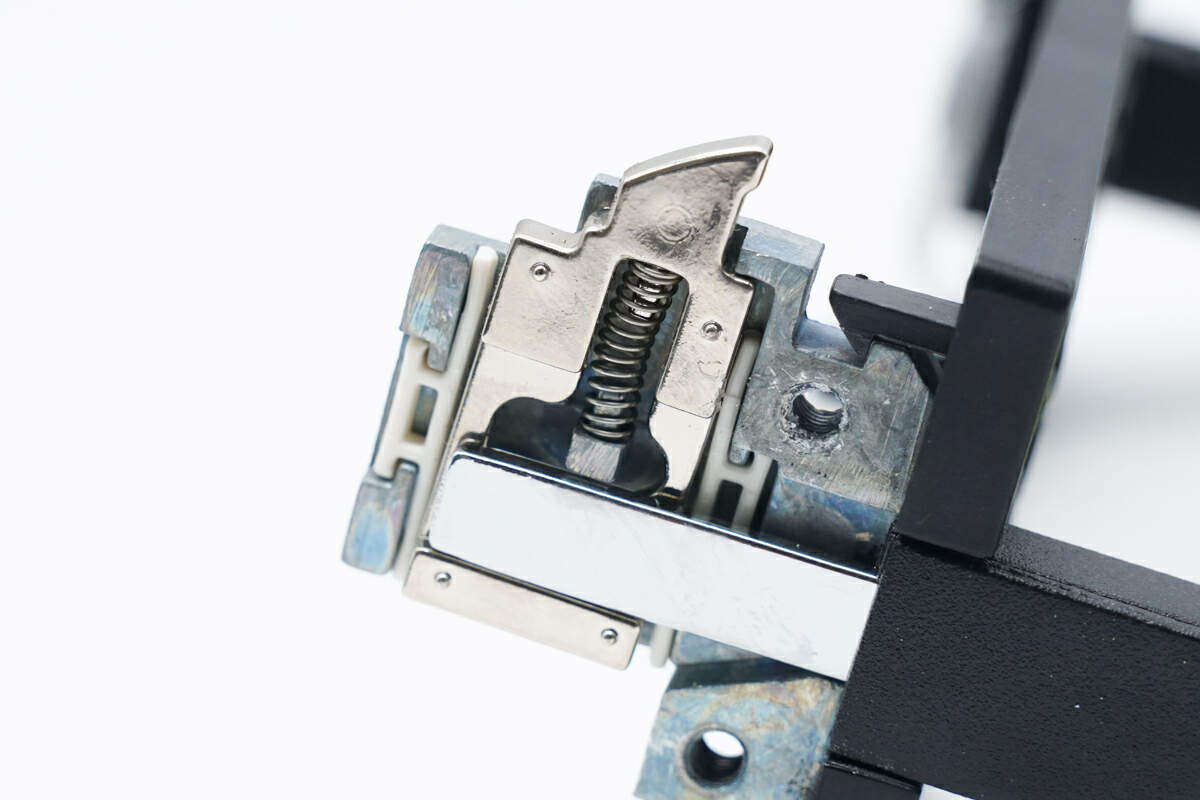
Close up of power module locking mechanism, with built-in spring return.
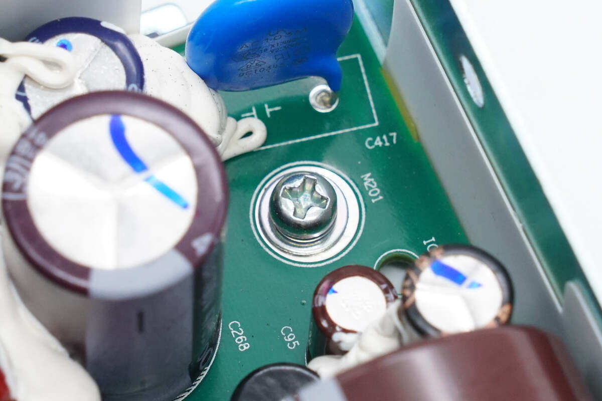
The PCBA module is fixed inside the housing by screws.
Take out the PCBA module, and provide Mylar insulation inside the shell.
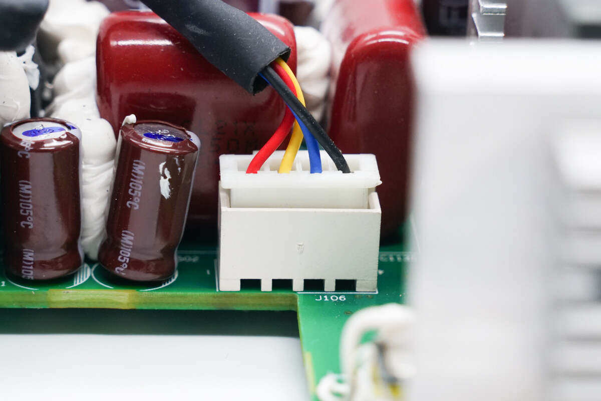
The cooling fan is connected through connectors.
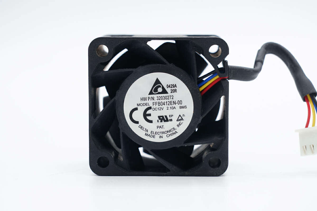
The cooling fan is from Delta, model FFB0412EN-00, specification 12V 2.1A, made in China.
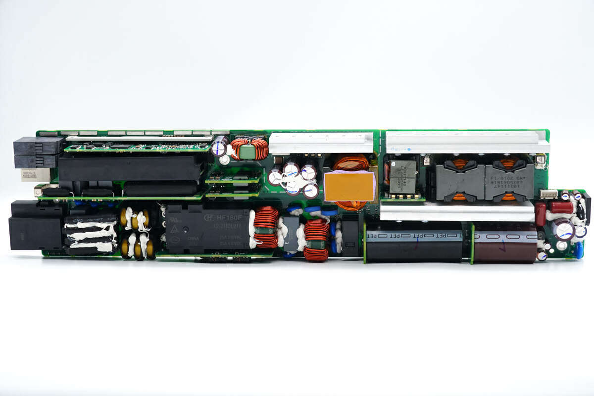
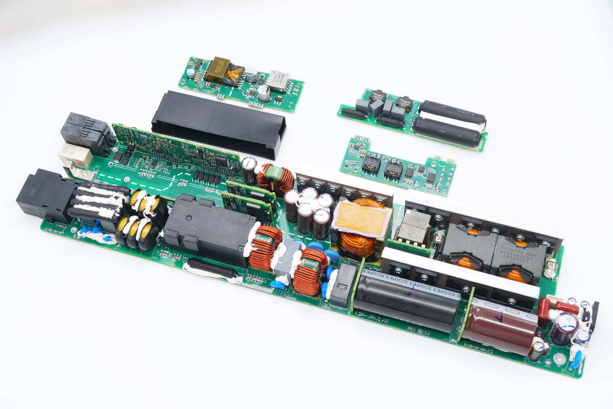
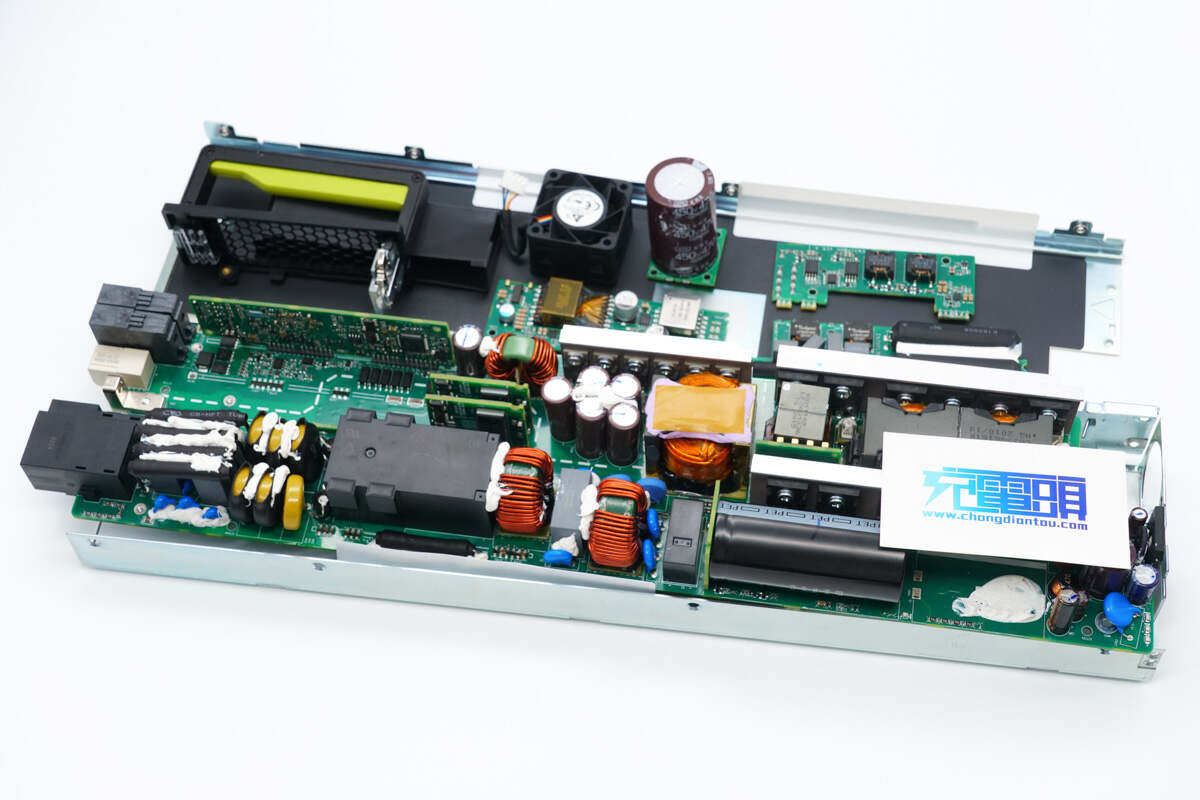
The front of the PCBA module is at a glance, and the lower left corner is the power input terminal, welding fuse, varistor, relay, common mode inductance, safety gauge X2 capacitor.Weld the high-voltage filter capacitor at the lower right corner.The heat sink above the high-voltage filter capacitor is provided with a switch tube and two rectifier bridges.PFC boost inductor, resonant inductor and resonant capacitor small plate are welded above the radiator, and switch tube, PFC switch tube and PFC rectifier tube are welded at the top.
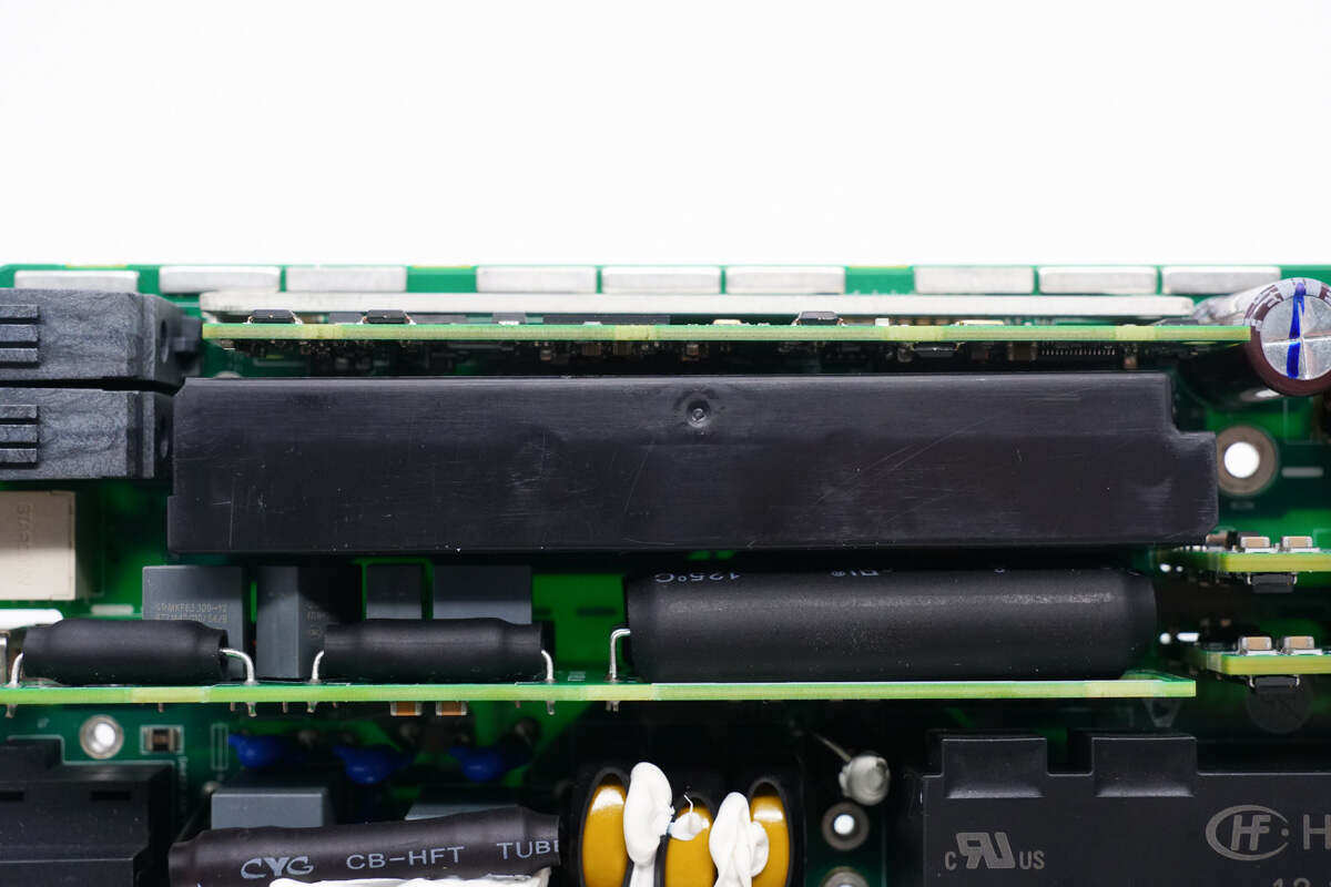
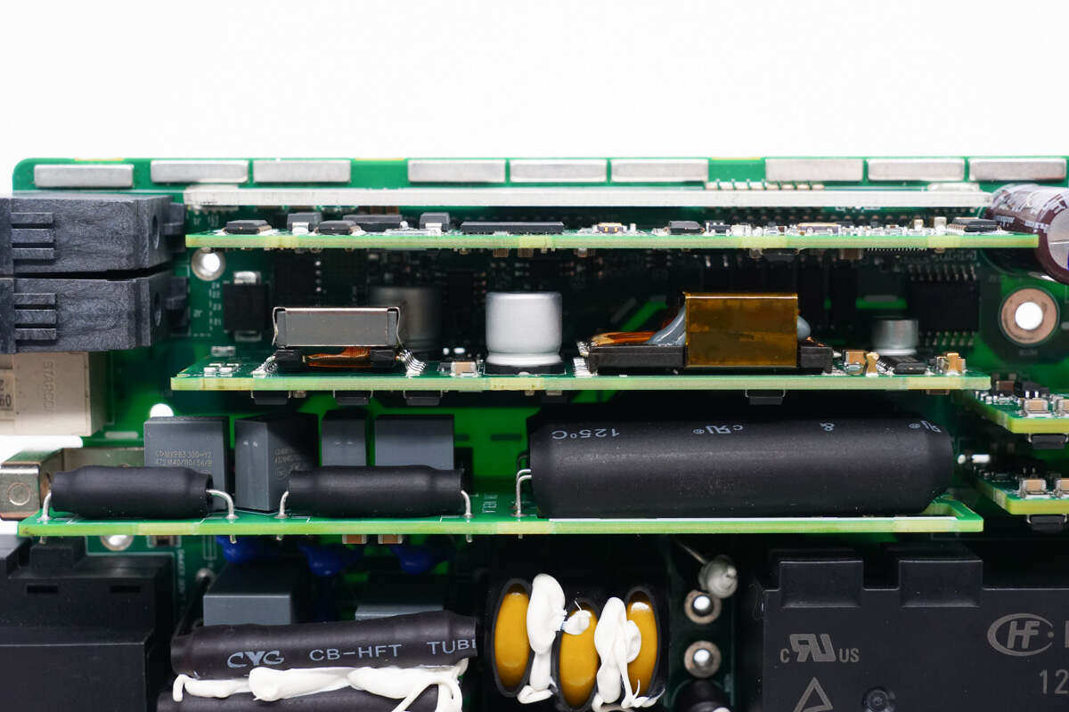
The upper left side is equipped with a main power control panel, the lower auxiliary power panel is insulated with a plastic cover, and the right side is welded with two auxiliary power panels.The small heat sink in the middle is a synchronous rectifier tube for heat dissipation, and the lower part is an output filter capacitor and transformer.The top of the transformer core is equipped with a heat conduction pad to enhance heat dissipation through the module cover plate, so as to reduce the temperature rise.
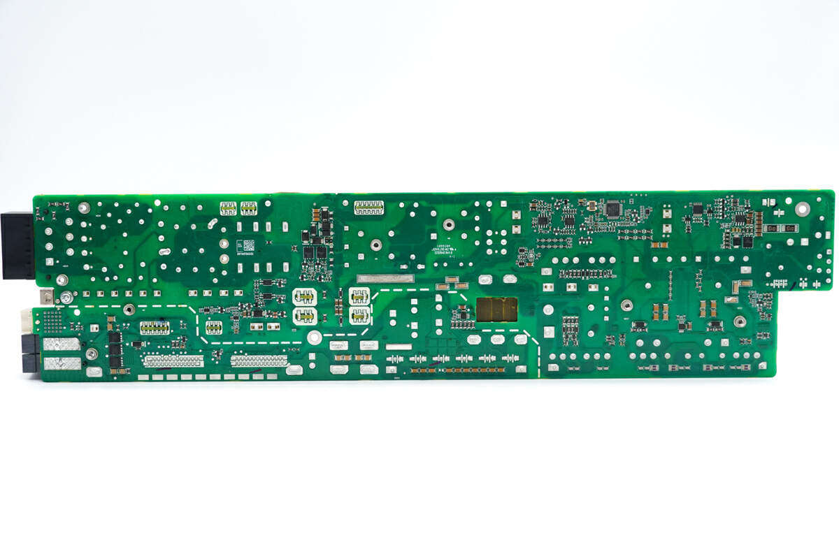
Components such as MCU and VBUS switch tube are set on the back of PCBA module, and the primary stages are distinguished by dotted lines.
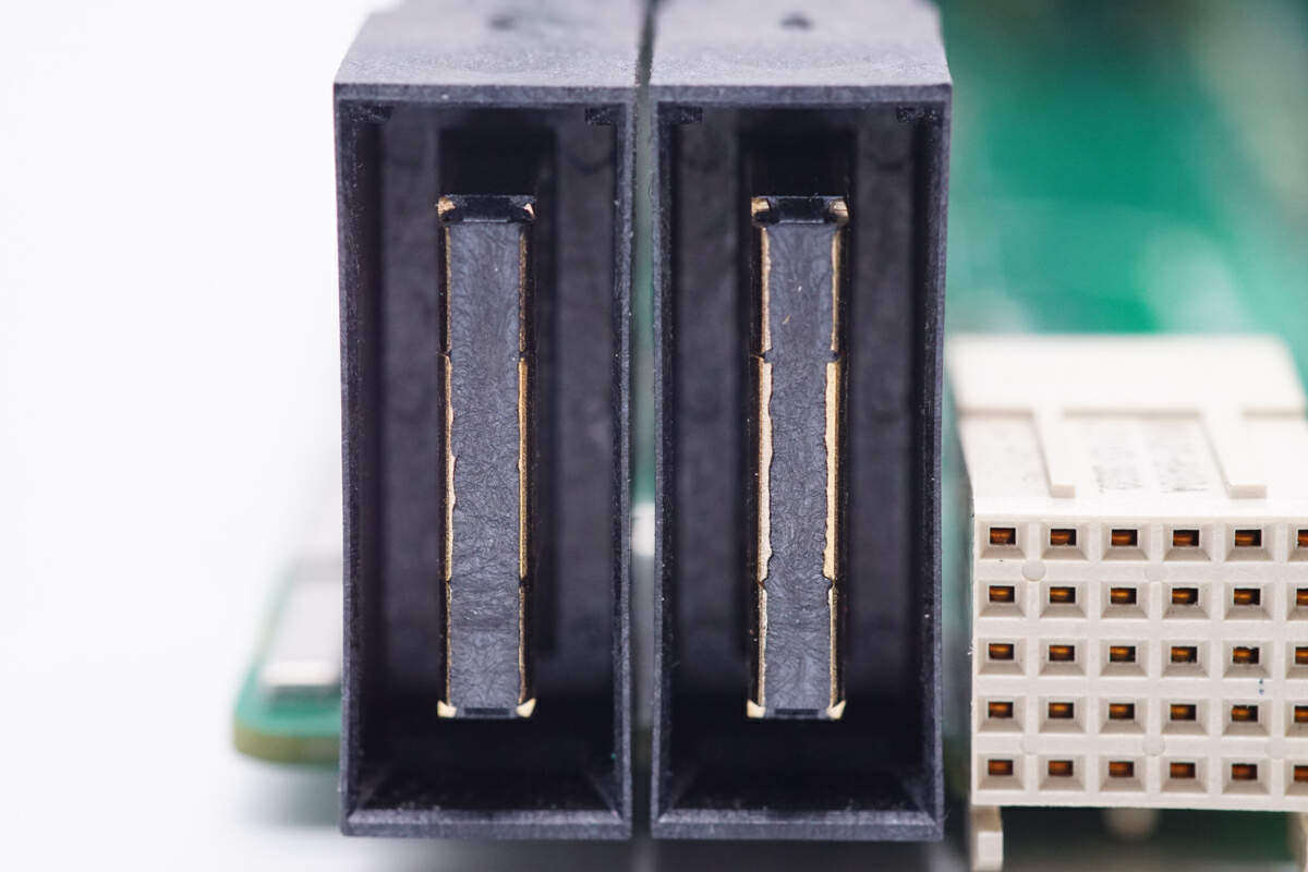
A list of the input and output terminals of the power module. The left vertical terminal is the power supply positive and negative pole output, and the right side is the power supply input terminal.
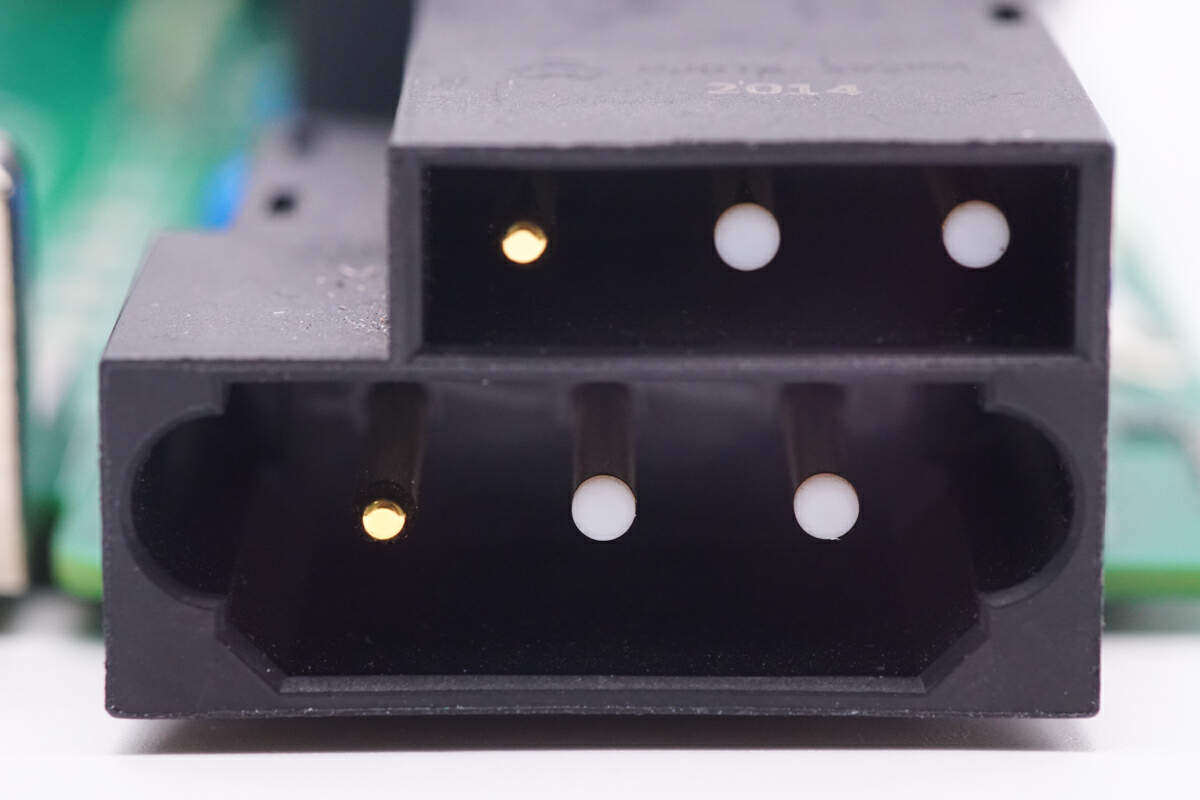
Close up of power input terminal, designed for upper and lower layers.
Close up of input fuse, insulated with heat shrink tube and fixed with glue.
Below the fuse is the safety gauge X2 capacitor, from Xiamen Farad Electronics, with the specification of 2.2μF。
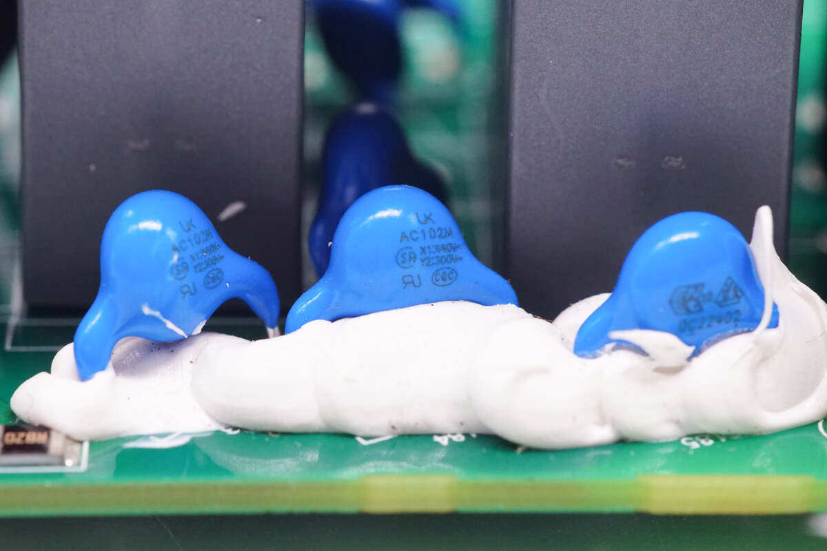
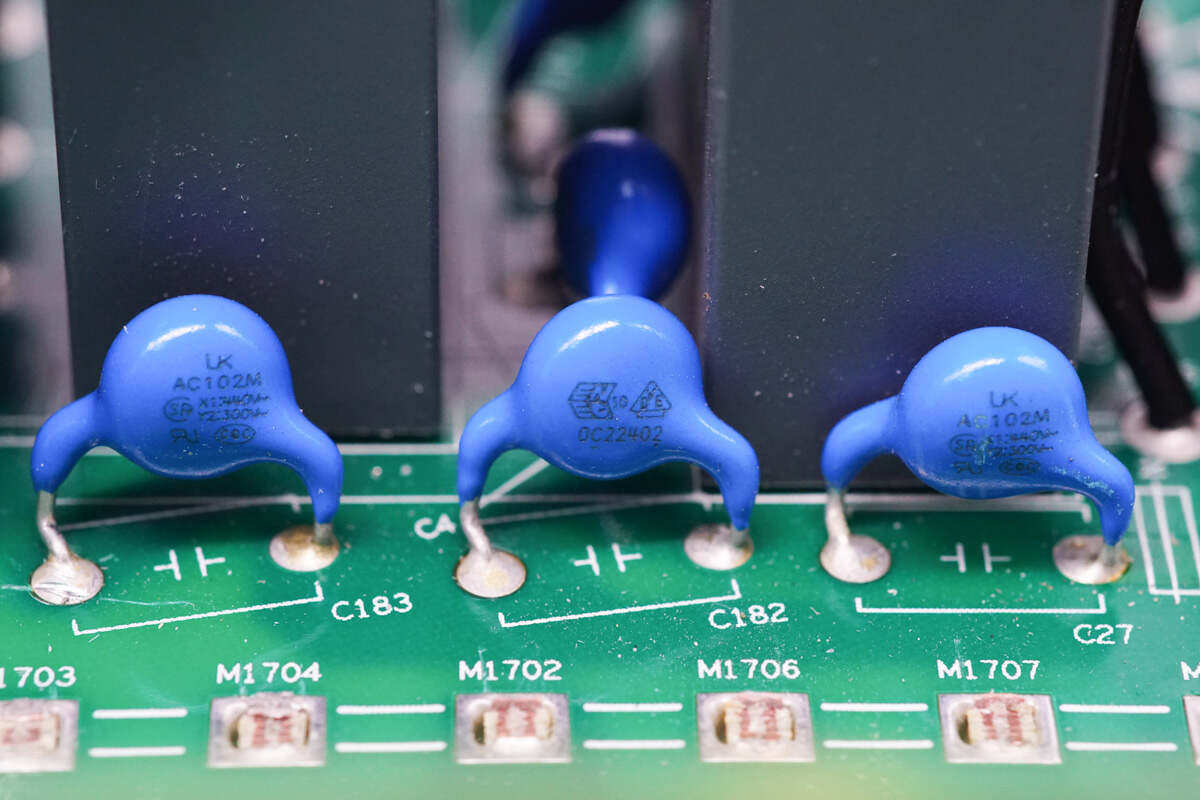
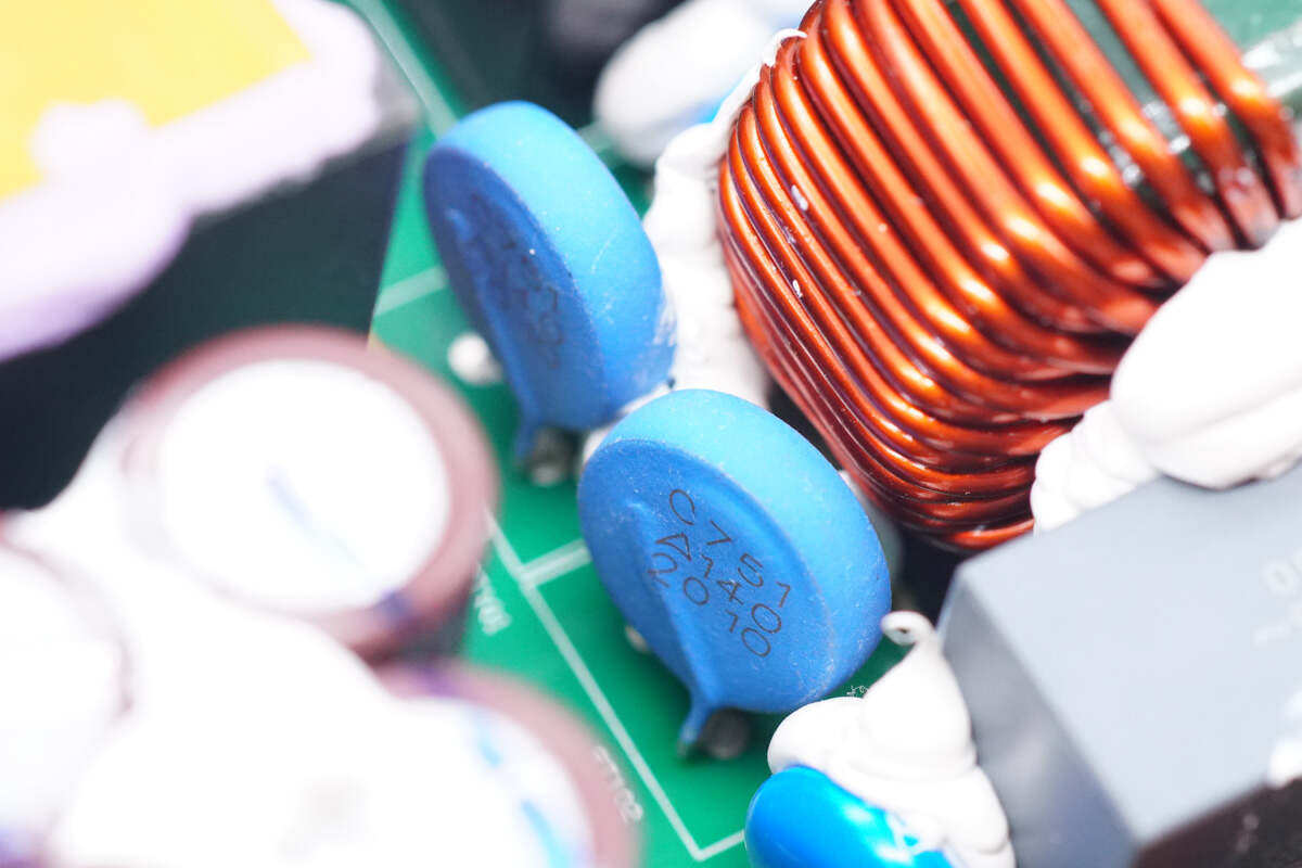
The blue safety regulation Y capacitor is from Huaxinke.
Close up of three blue Y capacitors at the other end.
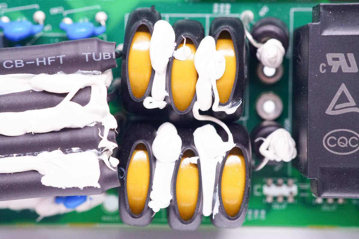
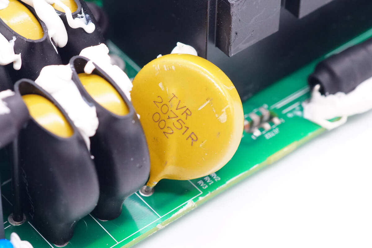
Six yellow varistors are used for surge absorption and insulated with heat shrinkable tubes.
The varistor model is TVR20751R.
Two gas discharge tubes are insulated by heat shrinkable tubes.
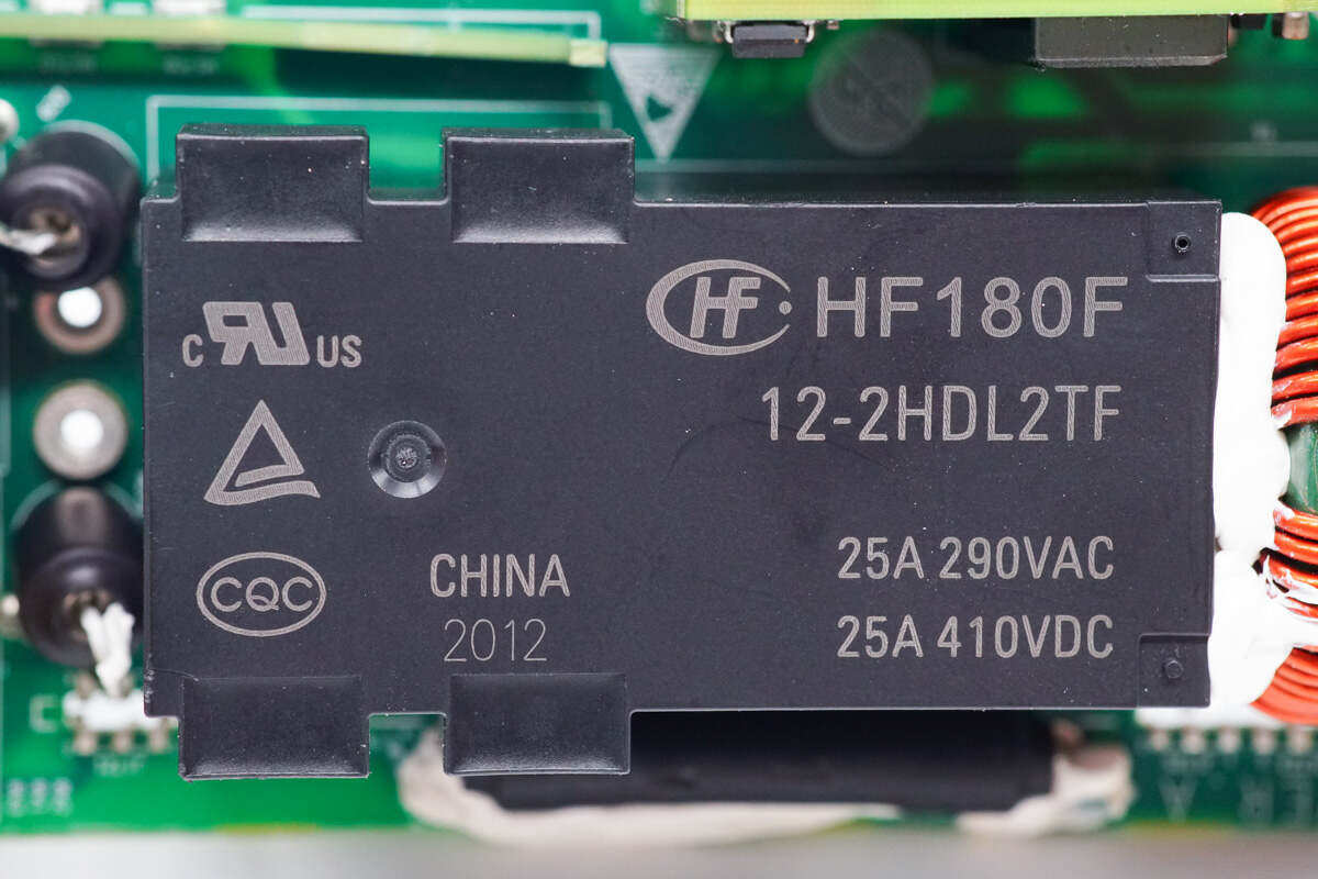
The relay is HF180F series magnetic latching relay from Hongfa, with coil voltage of 12V, two sets of normally open+normally closed contacts built in, and contact capacity of 25A 290VAC.
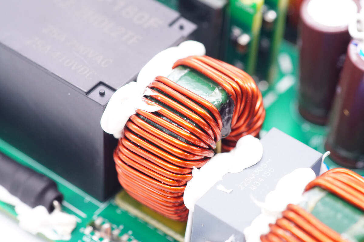
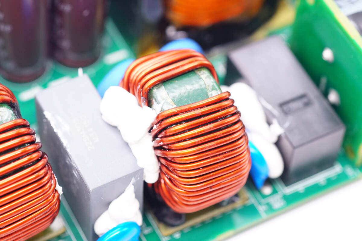
The common mode inductor is made of magnetic ring winding, and bakelite board insulation is set between it and PCB.
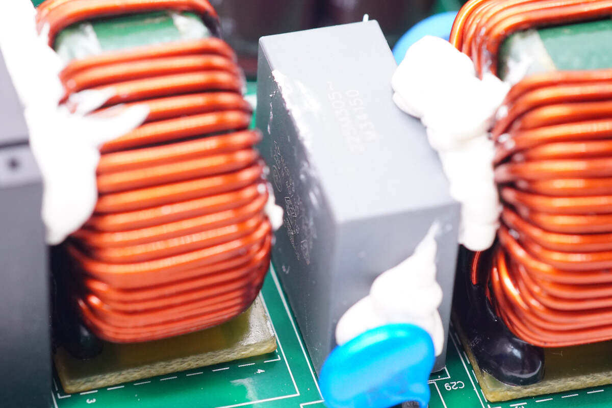
Close up of gray safety capacitance.
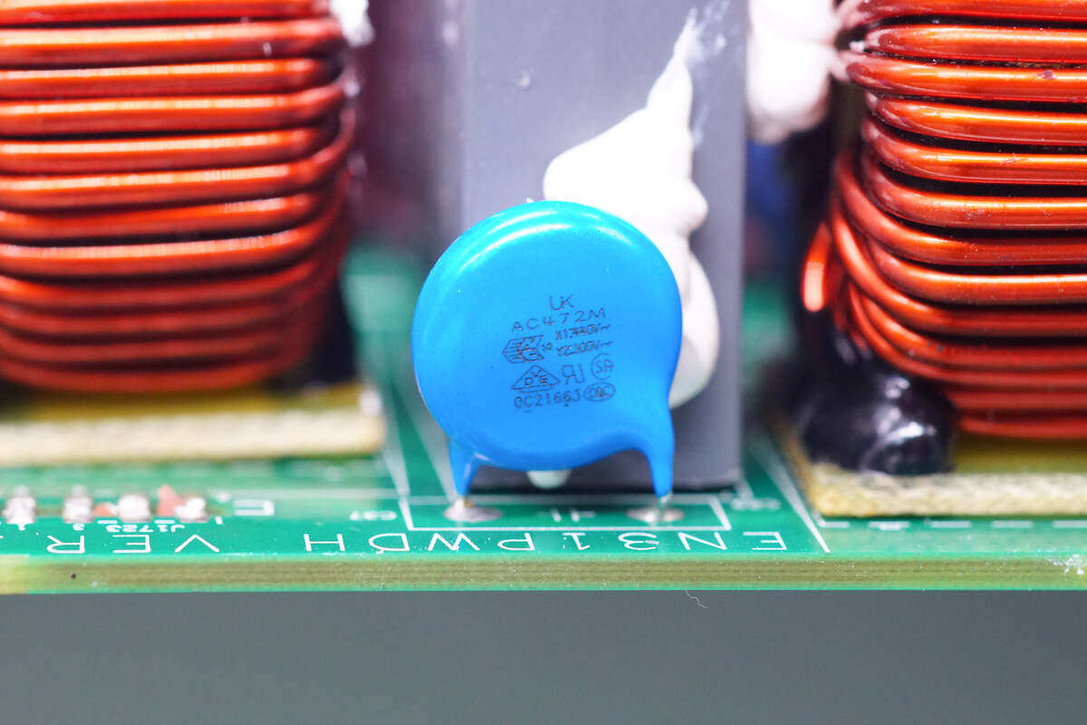
Close up of blue Y capacitor.
The other common mode inductor is also wound by magnetic ring, and the bottom is fixed with electric board for insulation.
Two thermistors are used to restrain the surge current of power supply.
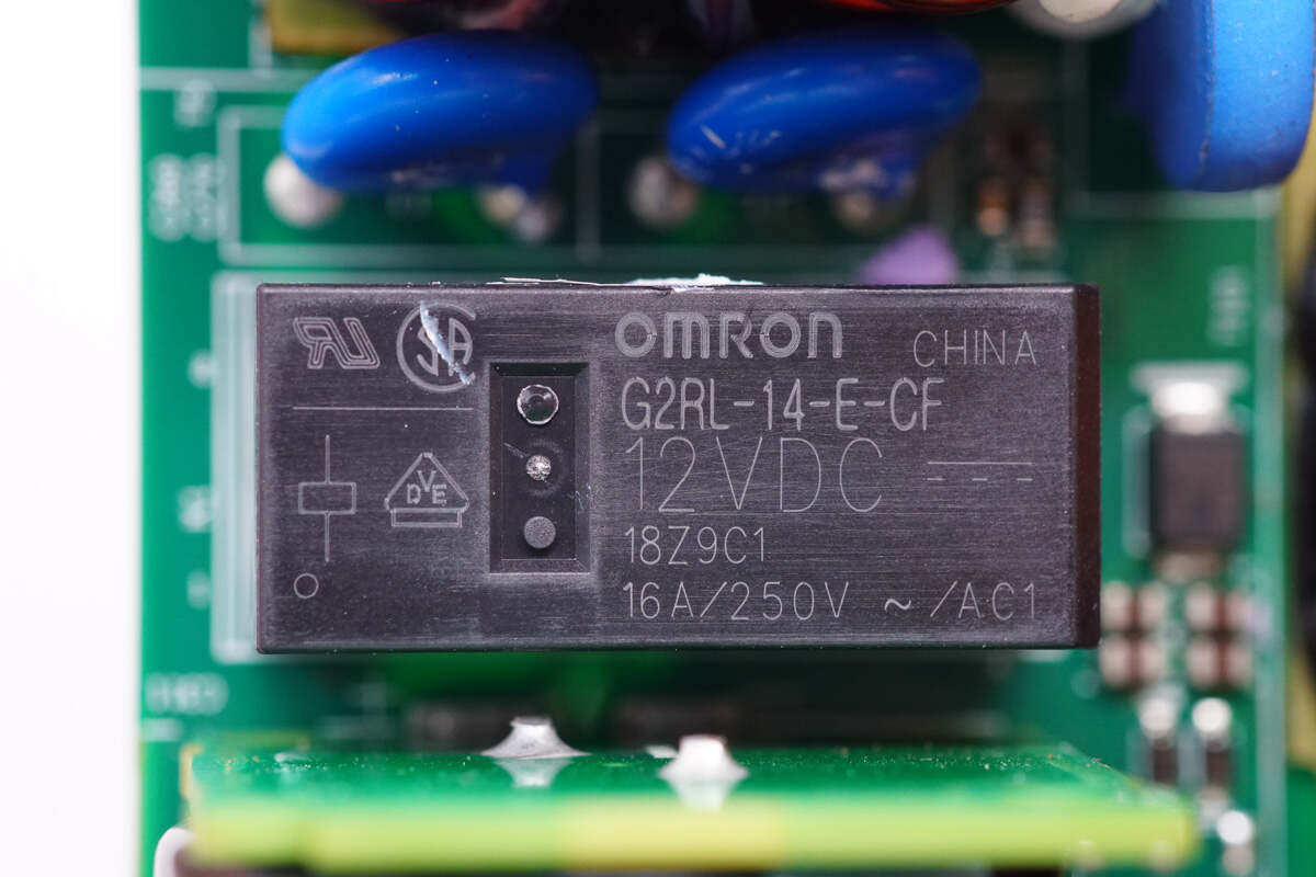
The relay for switching thermistor is from Omron, model G2RL-14-E-CF, coil voltage 12V, contact capacity 16A/250V.
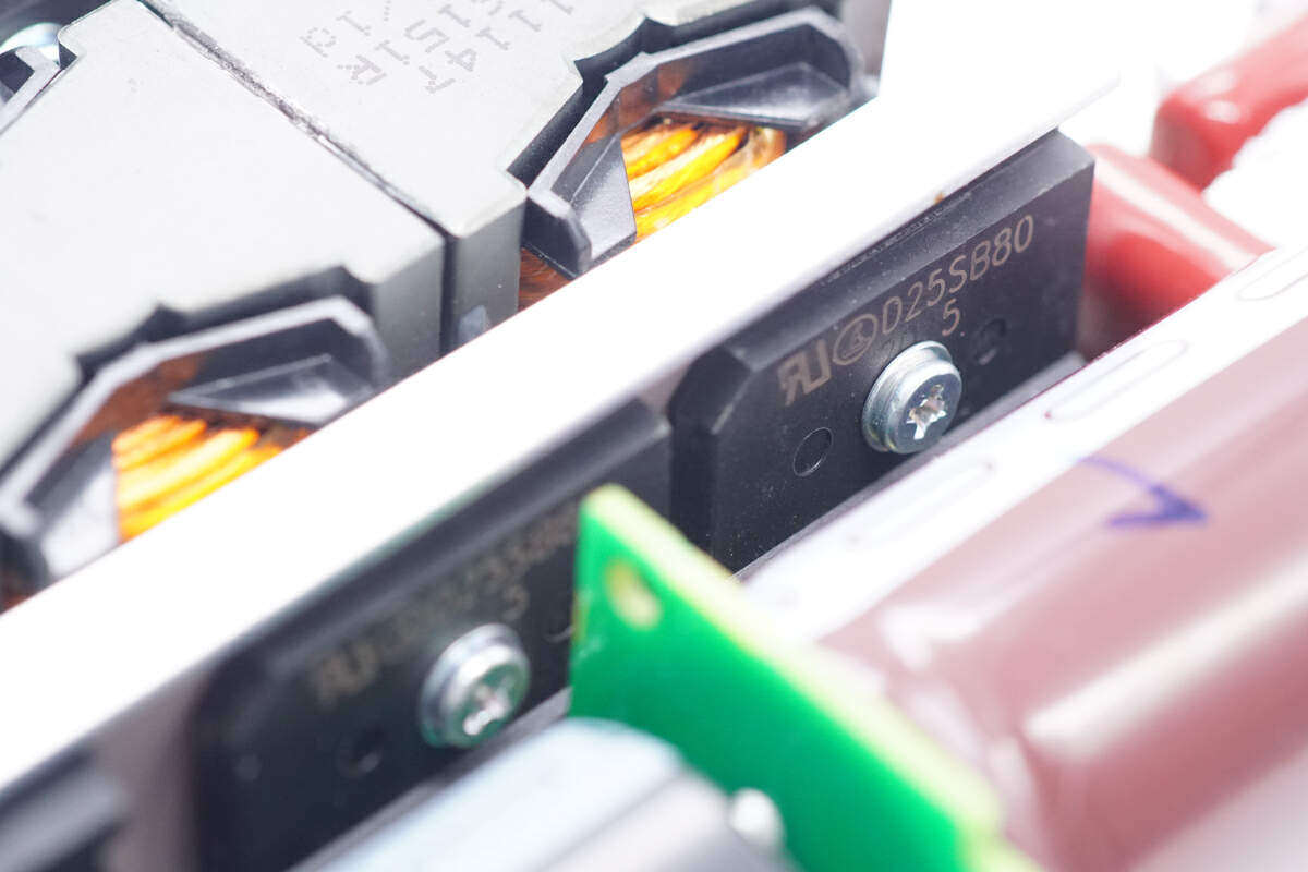
Two rectifier bridges are from Leshan Radio, model D25SB80, specification 25A 800V, and two half bridges are connected to generate heat evenly.
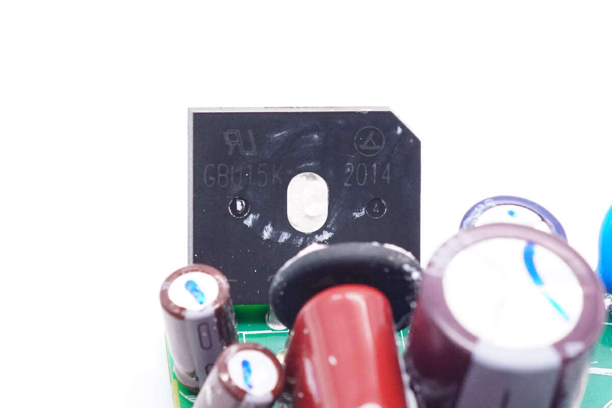
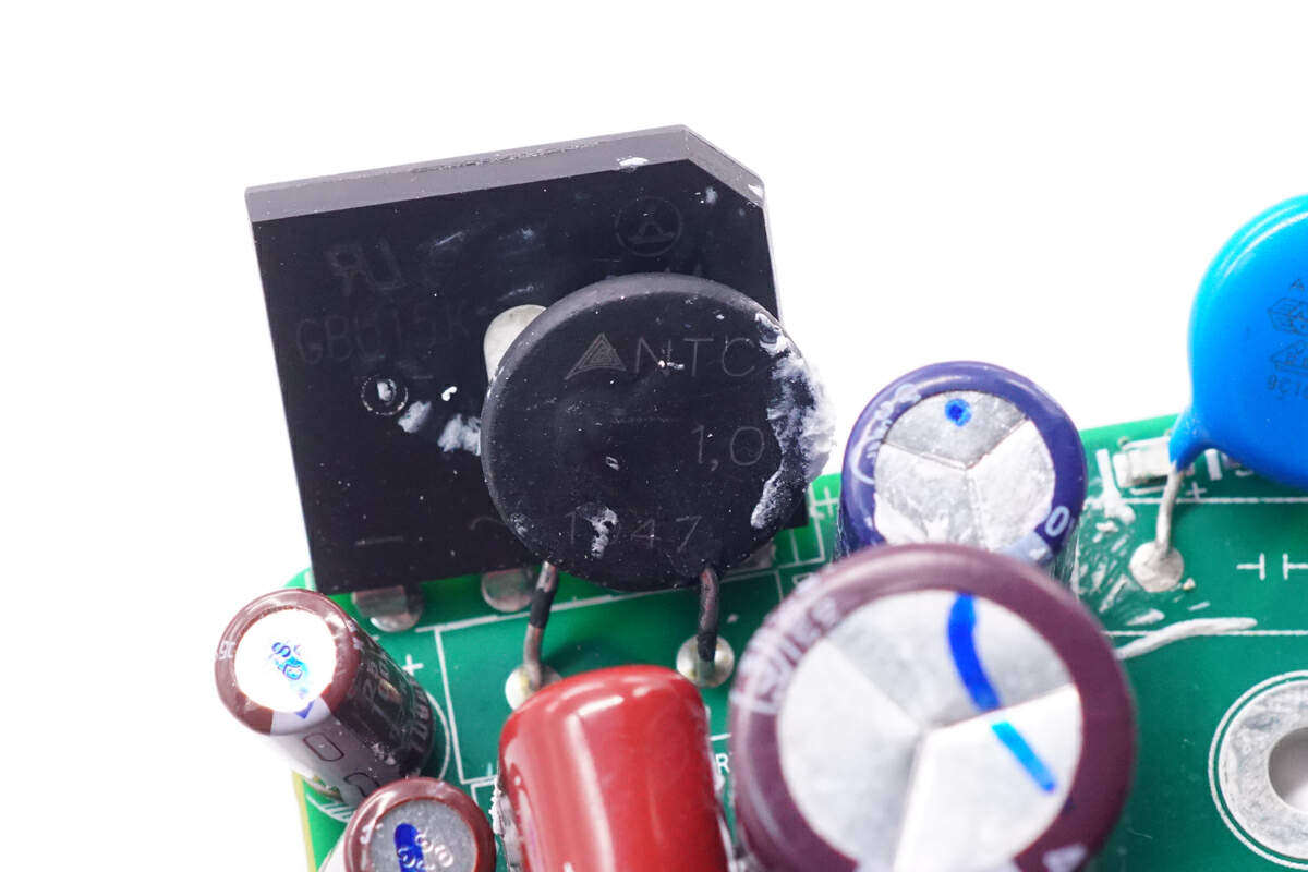
In addition, there is also a rectifier bridge from Leshan Radio, model GBU15K, specification 15A 800V
The front end of the rectifier bridge is equipped with an NTC thermistor.
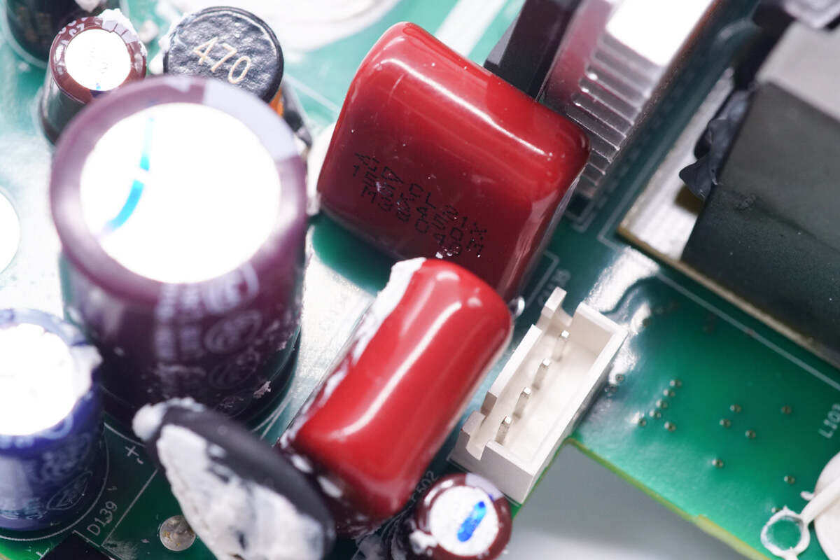
The film filter capacitor is from Xiamen Farad Electronics, CL21X series, and the specification is 1.5μF450V。
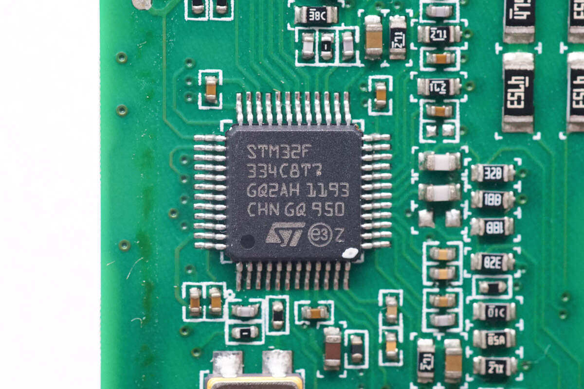
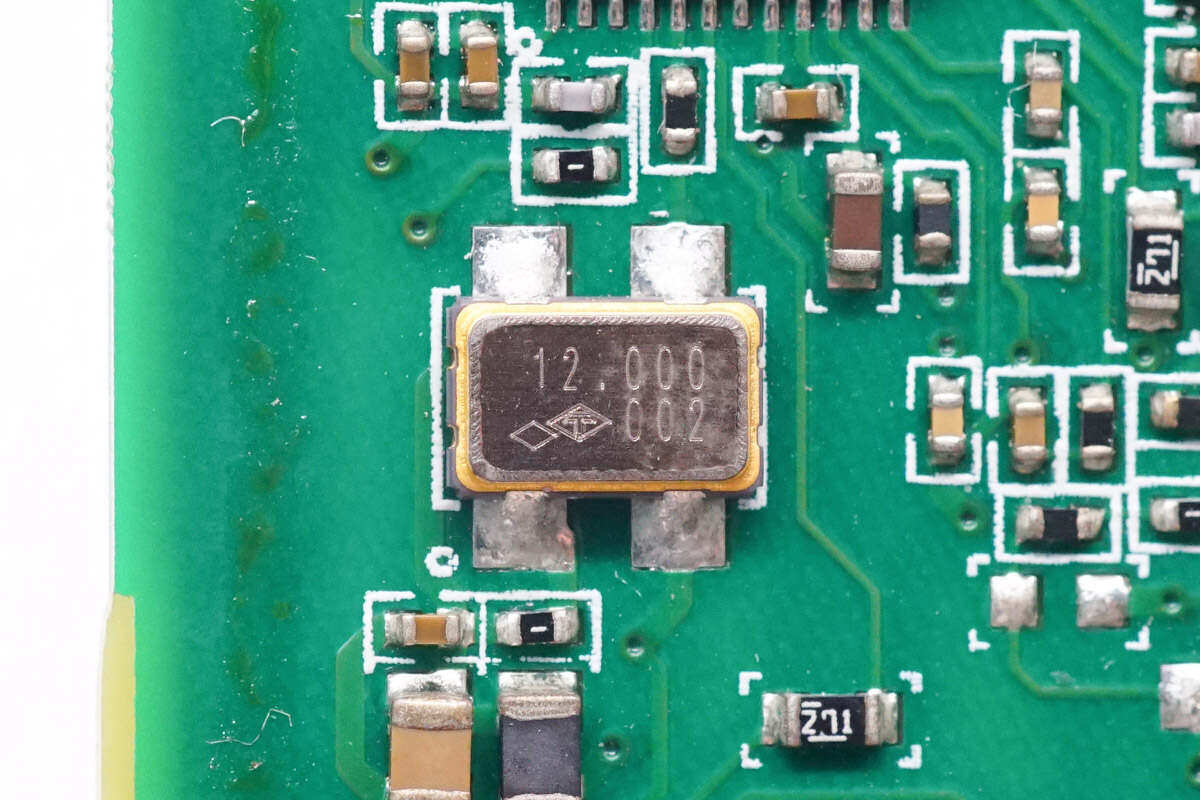
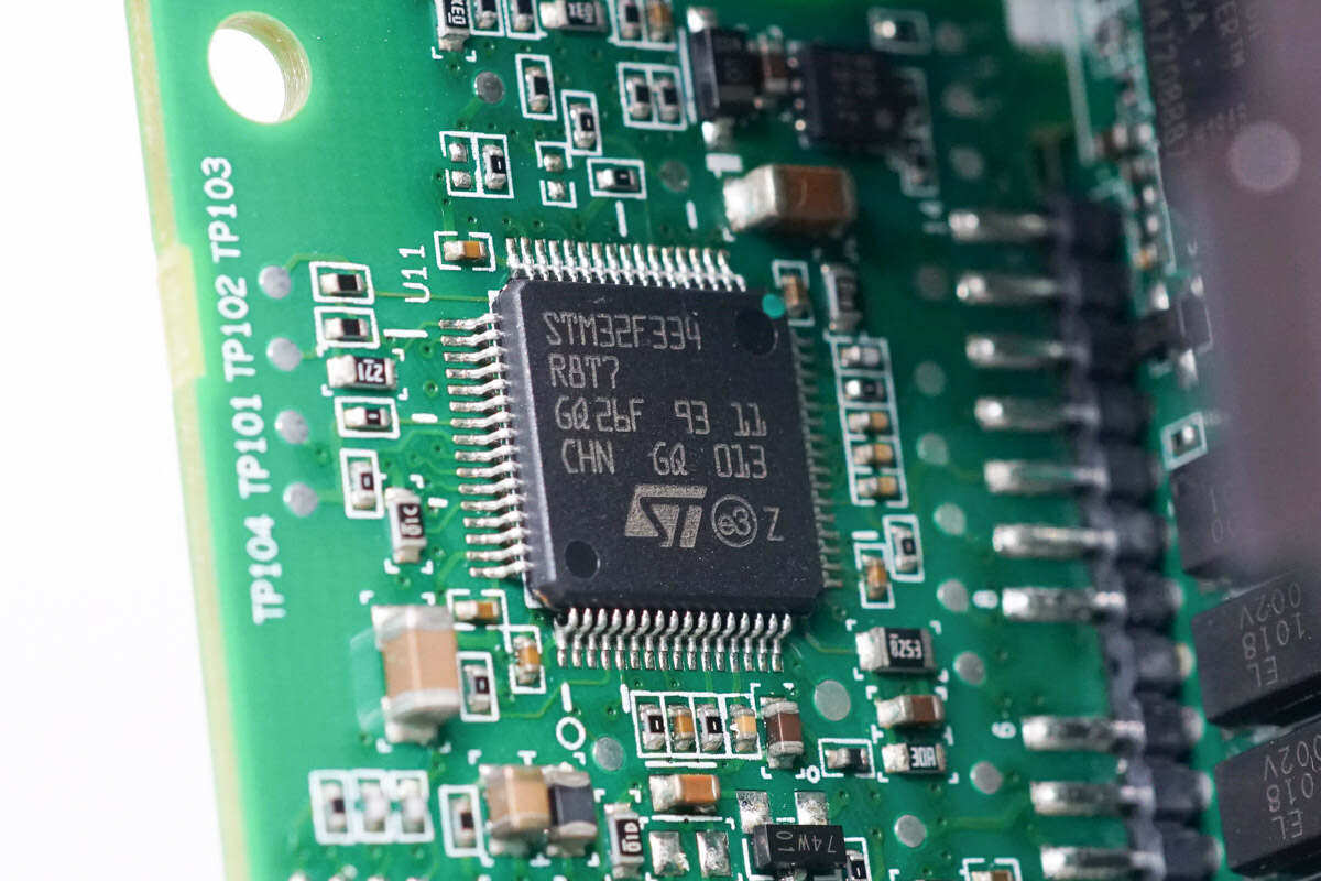
The power supply master MCU chip is from ST Italy, and the model is STM32F334C8T7. The chip has a built-in 32-bit CPU and FPU, the main frequency is up to 72MHz, the built-in 64K FLASH and 12K SRAM, and supports parity check.It also integrates two fast 12 bit ADC, ultra fast comparator, etc., and supports 6-channel PWM signal output.
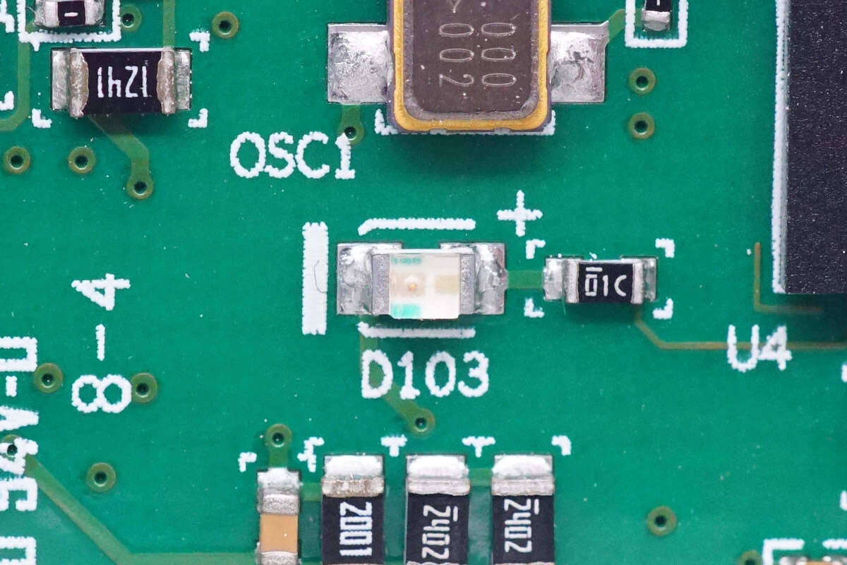
SMD crystal oscillator frequency is 12.000MHz.
PFC switch tube and rectifier tube are set at the side of PFC boost inductor.
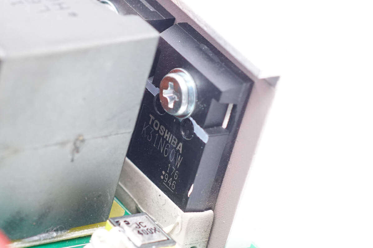
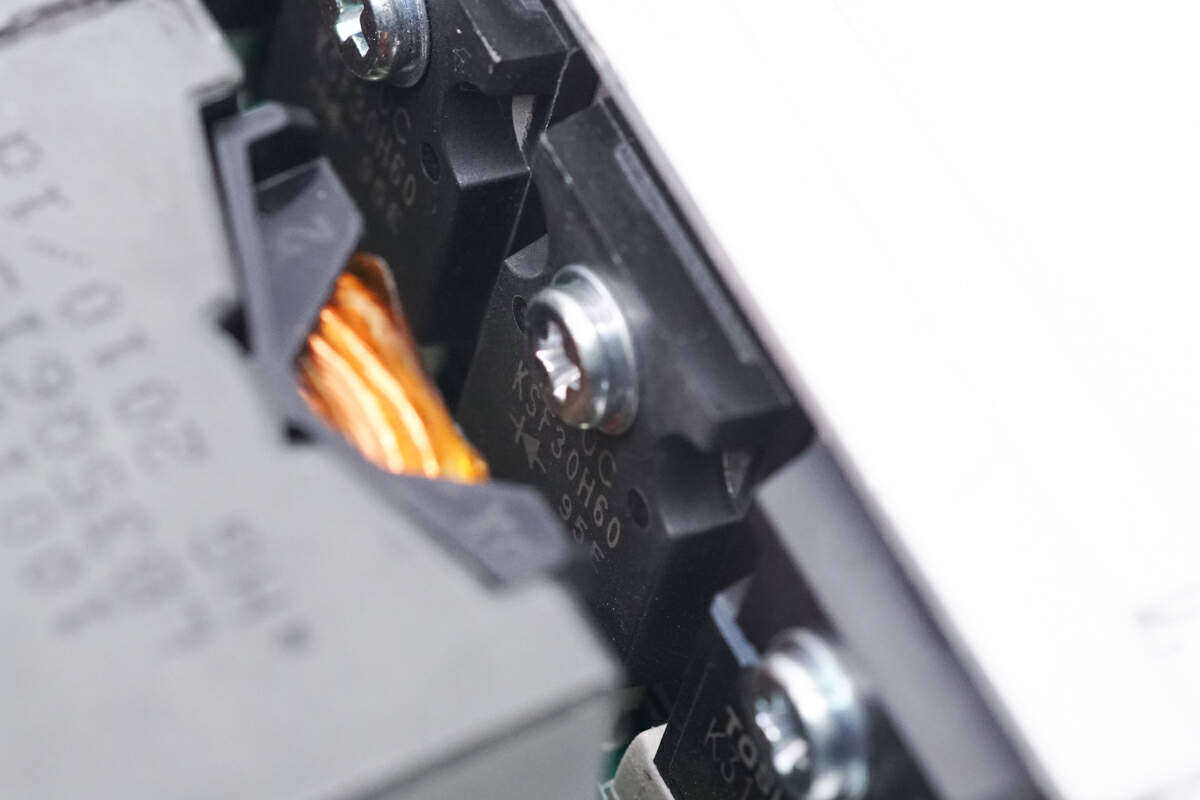
PFC switch tube is from Toshiba, with model of TK31N60W, NMOS, withstand voltage of 600V, resistance of 73m Ω, and TO247 package.
The two PFC boost inductors are made of Leeds wire.
PFC rectifier tube is from Kyocera, model KSH30H60, a fast recovery diode, specification 600V30A, and TO-247-2pin packaging.
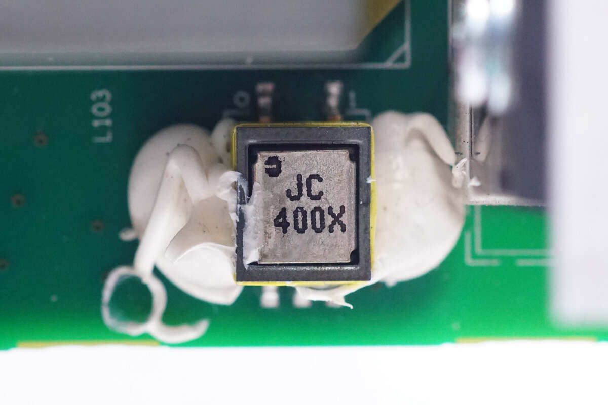
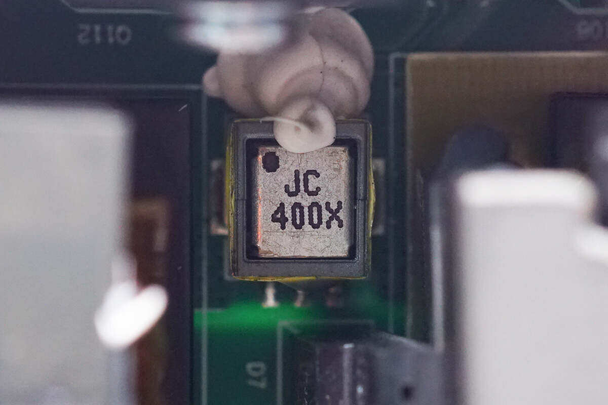
Close up of the transformer used to detect PFC current, and glue it for reinforcement.
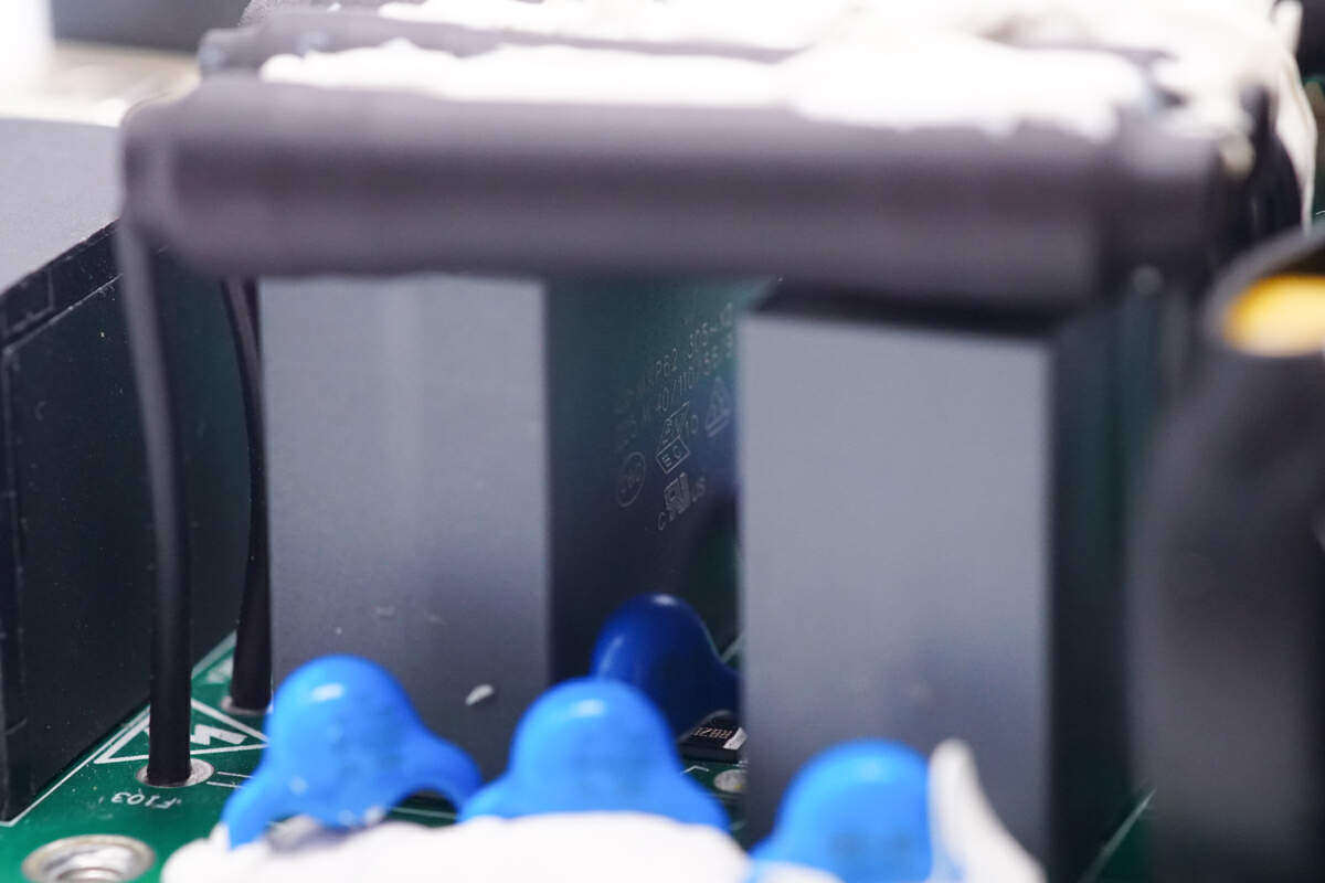
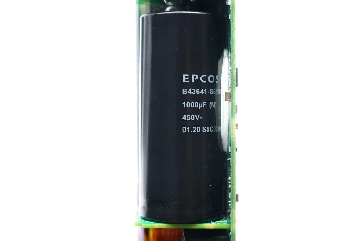
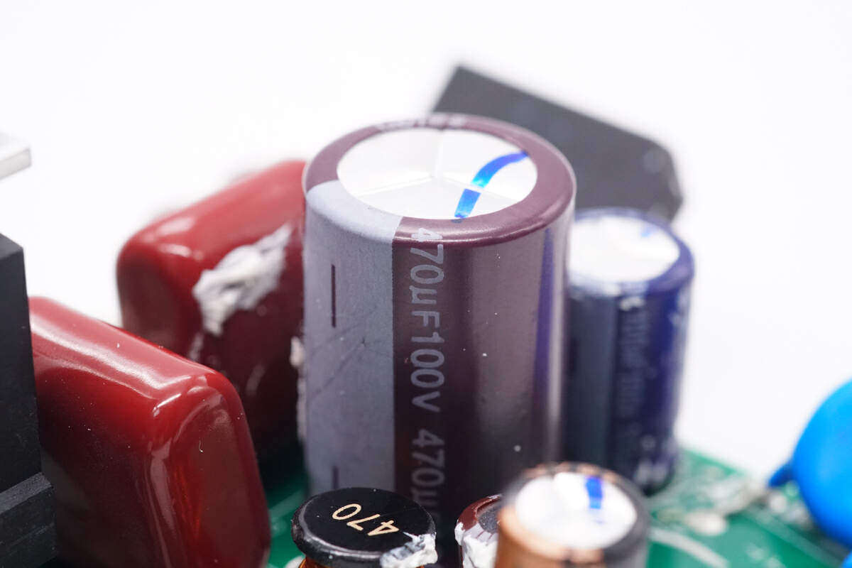
High voltage filter capacitor from EPCOS, specification 1000μF450V。
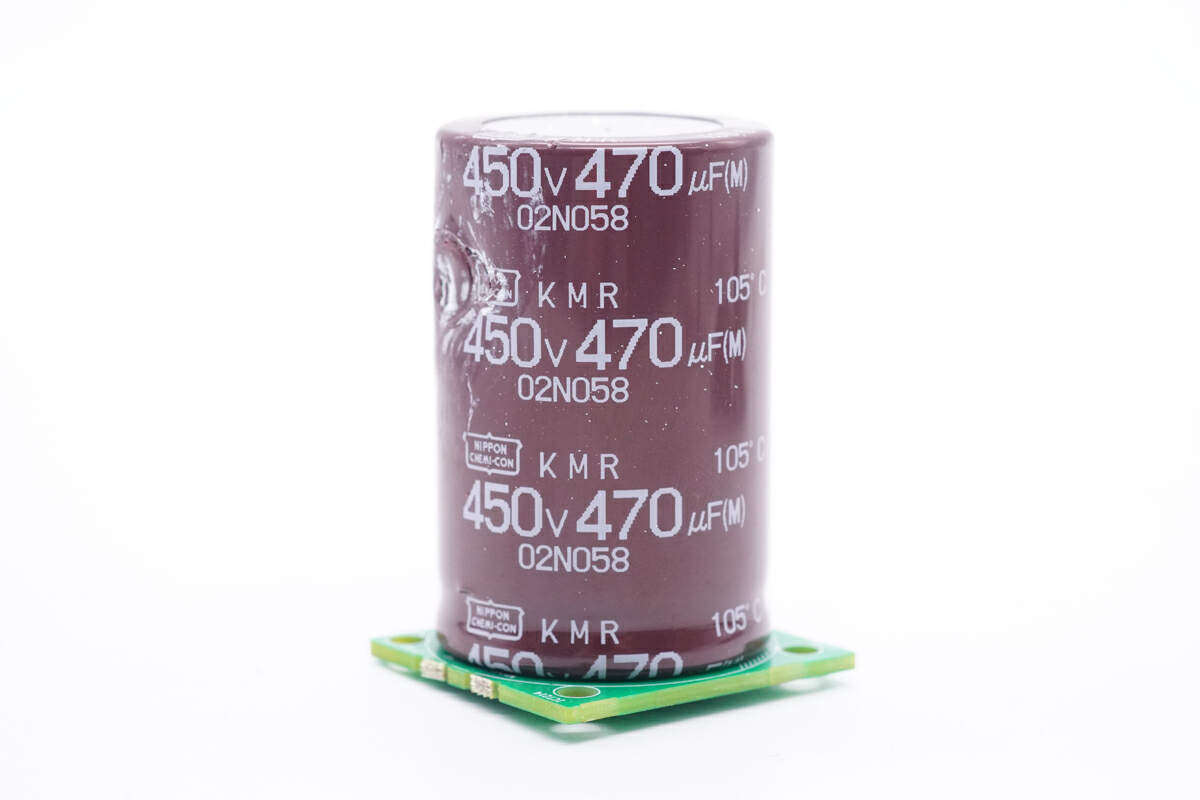
The other high-voltage filter capacitor is from Guimigong, and the specification is 450V470μF。
Weld a MCU from STM32F334R8T7 of STM32F334R8T7 on the small board on the side of PCBA module, which is a mixed signal MCU with built-in DSP and FPU, built-in Cortex-M4 CPU, main frequency up to 72MHz, built-in 64KB Flash and 16KB SRAM.
The heat sink of PFC switch tube is provided with two switch tubes.
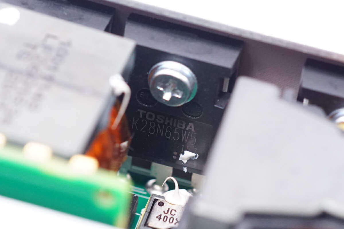
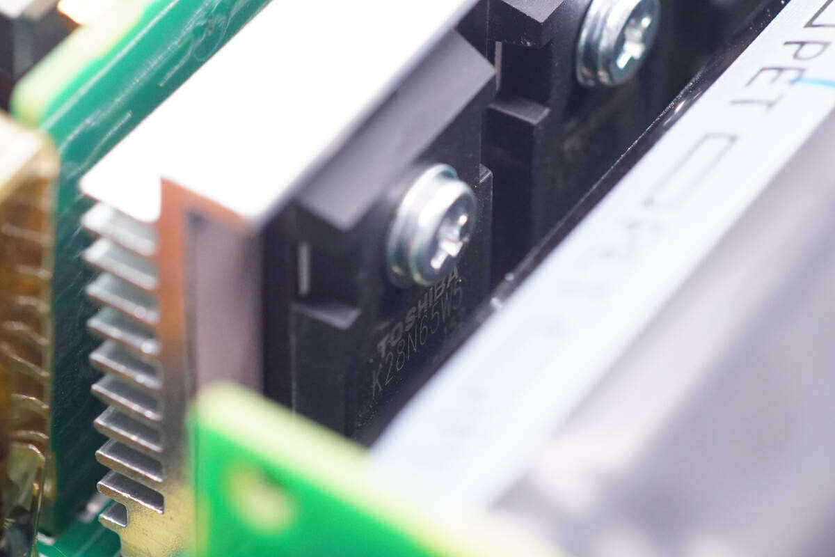
The switch tube is from Toshiba, model: TK28N65W5, NMOS, withstand voltage: 650V, resistance: 110m Ω, and TO-247 packaging.
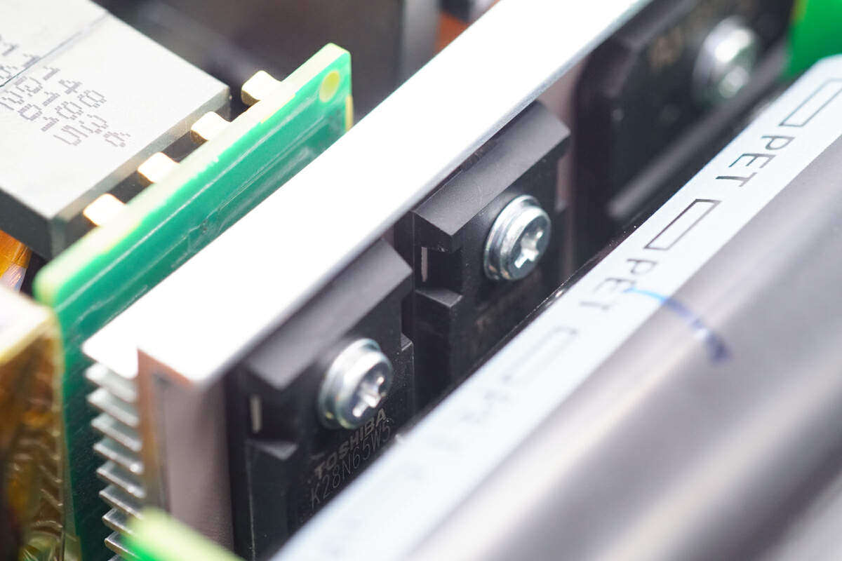
Two switch tubes are also fixed on the heat sink of the rectifier bridge.
The switch tube model is also TK28N65W5, and the four models are the same.
SMD current transformer is used for current detection.
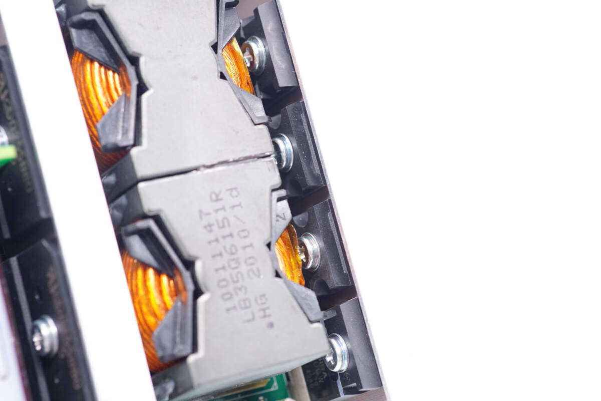
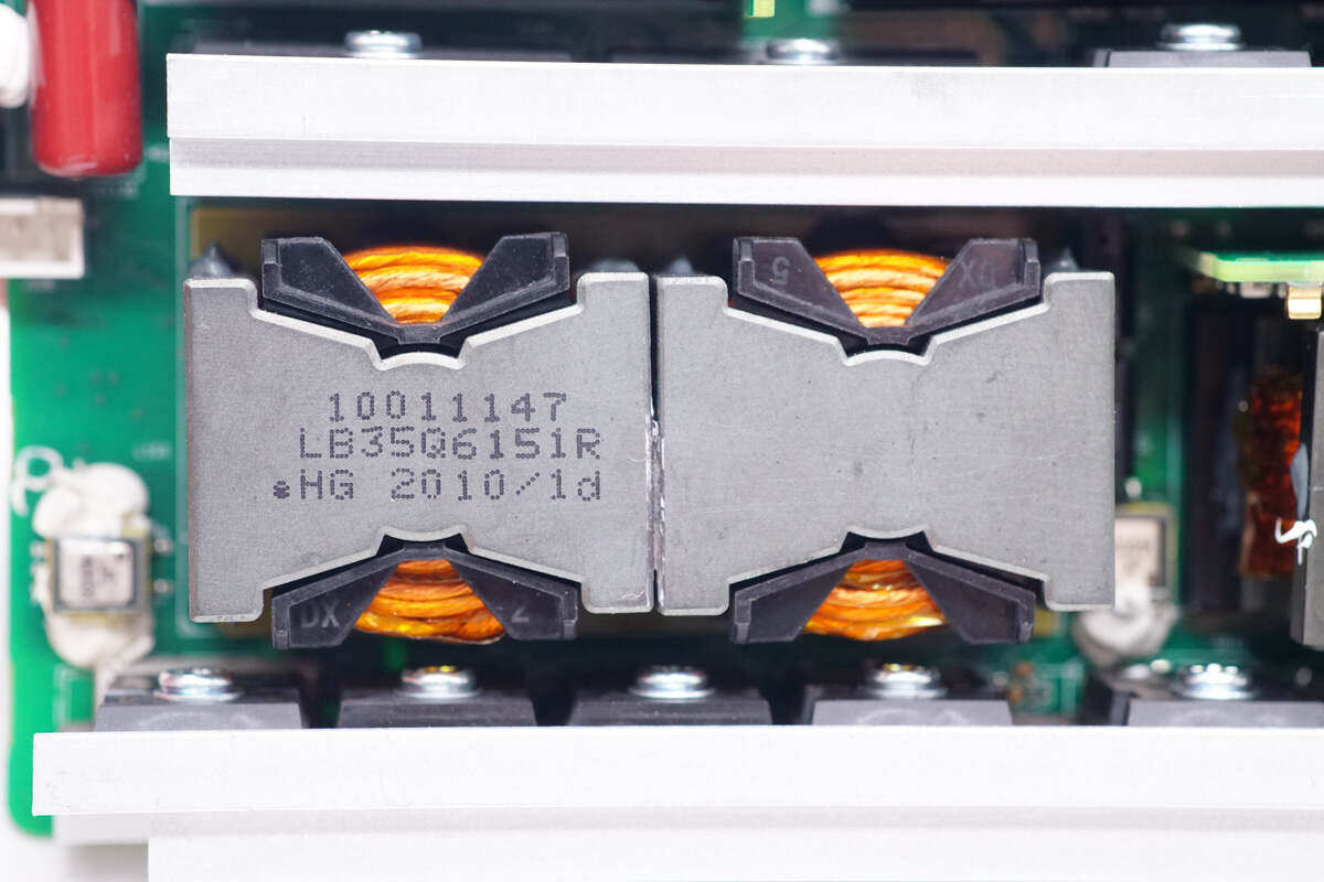
Close up of resonance inductance, magnetic core marking information.Weld the small resonant capacitor plate on the right side.
The resonant capacitor adopts MLCC, which is welded on the vertical small plate to save space.
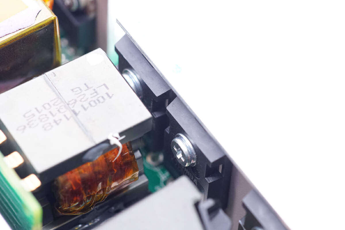
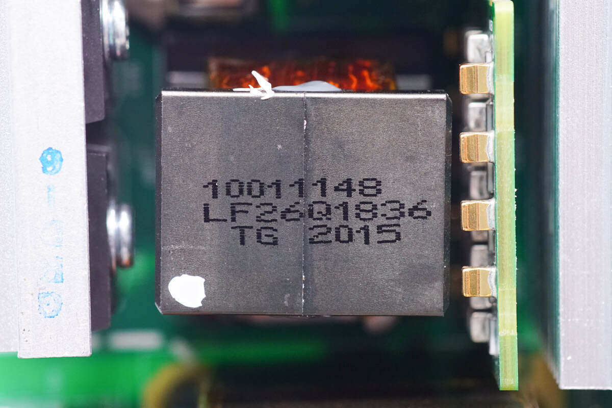
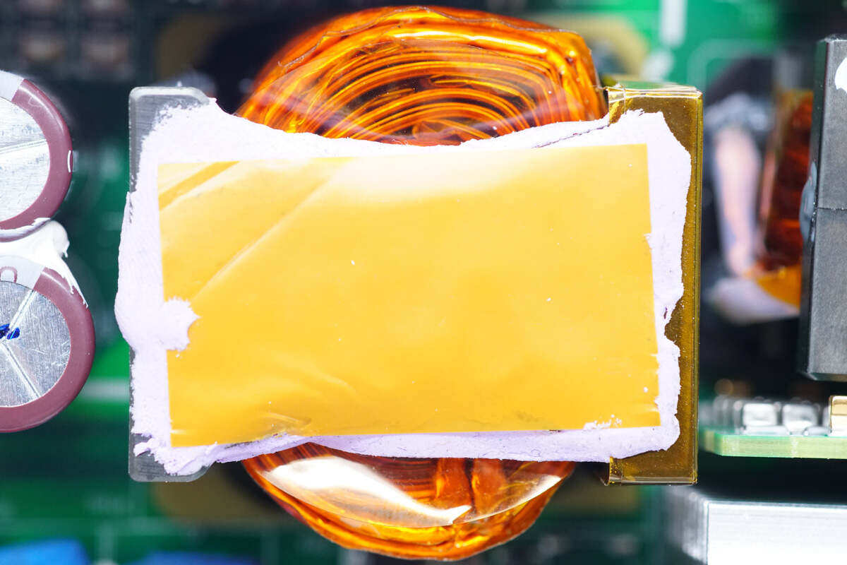
The transformer is wound with Leeds wire, and the magnetic core is pasted with a heat conduction pad and connected to the module cover plate to enhance heat dissipation.
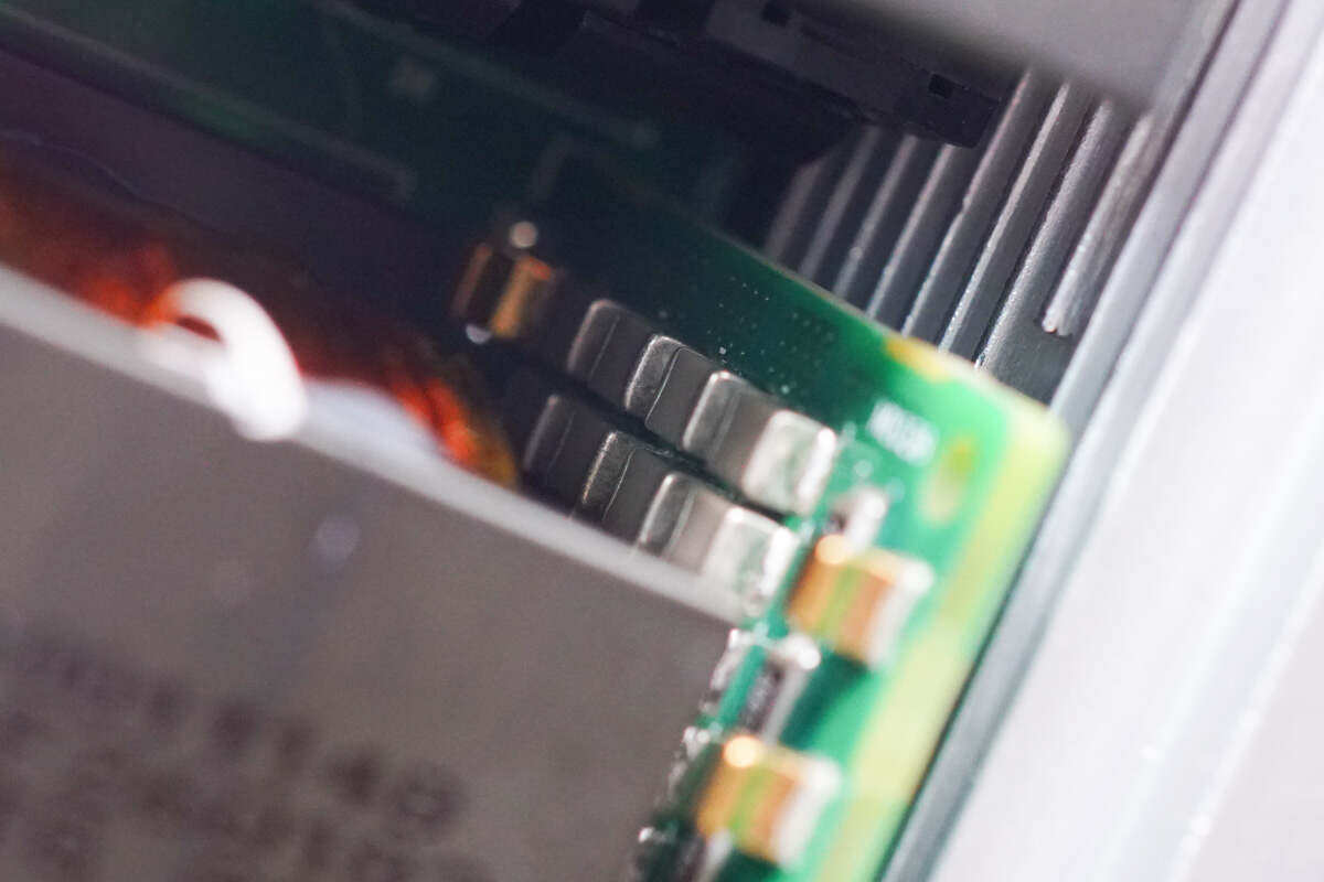
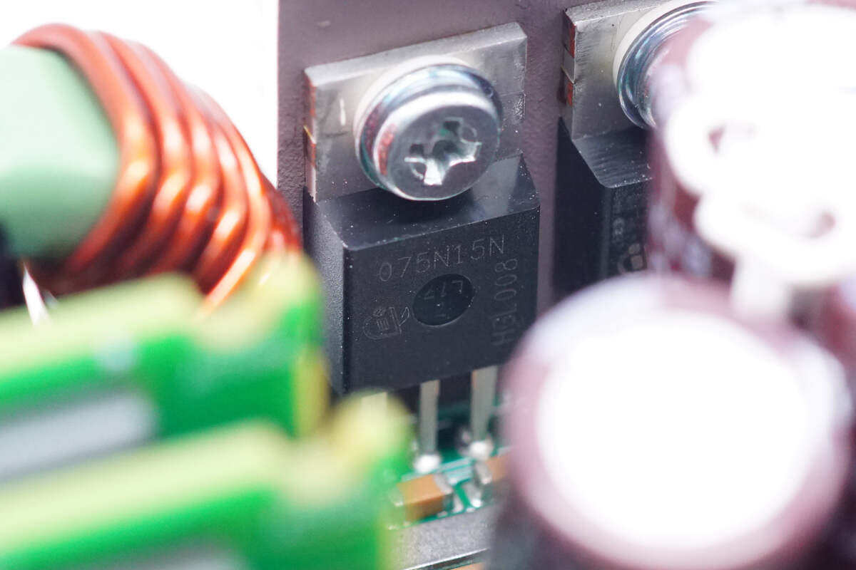
Six synchronous rectifier tubes at the output end are fixed on the heat sink.
The synchronous rectifier tube is from Infineon, with the model of IPP075N15N3, NMOS, withstand voltage of 150V, resistance of 7.2m Ω and PG-TO220-3 packaging.
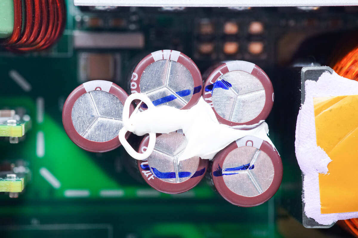
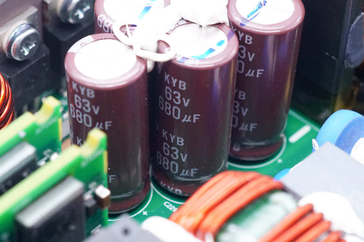
The five filter capacitors at the output end are fixed with glue.
The output filter capacitor specification is 63V680μF. 3400 in totalμF。
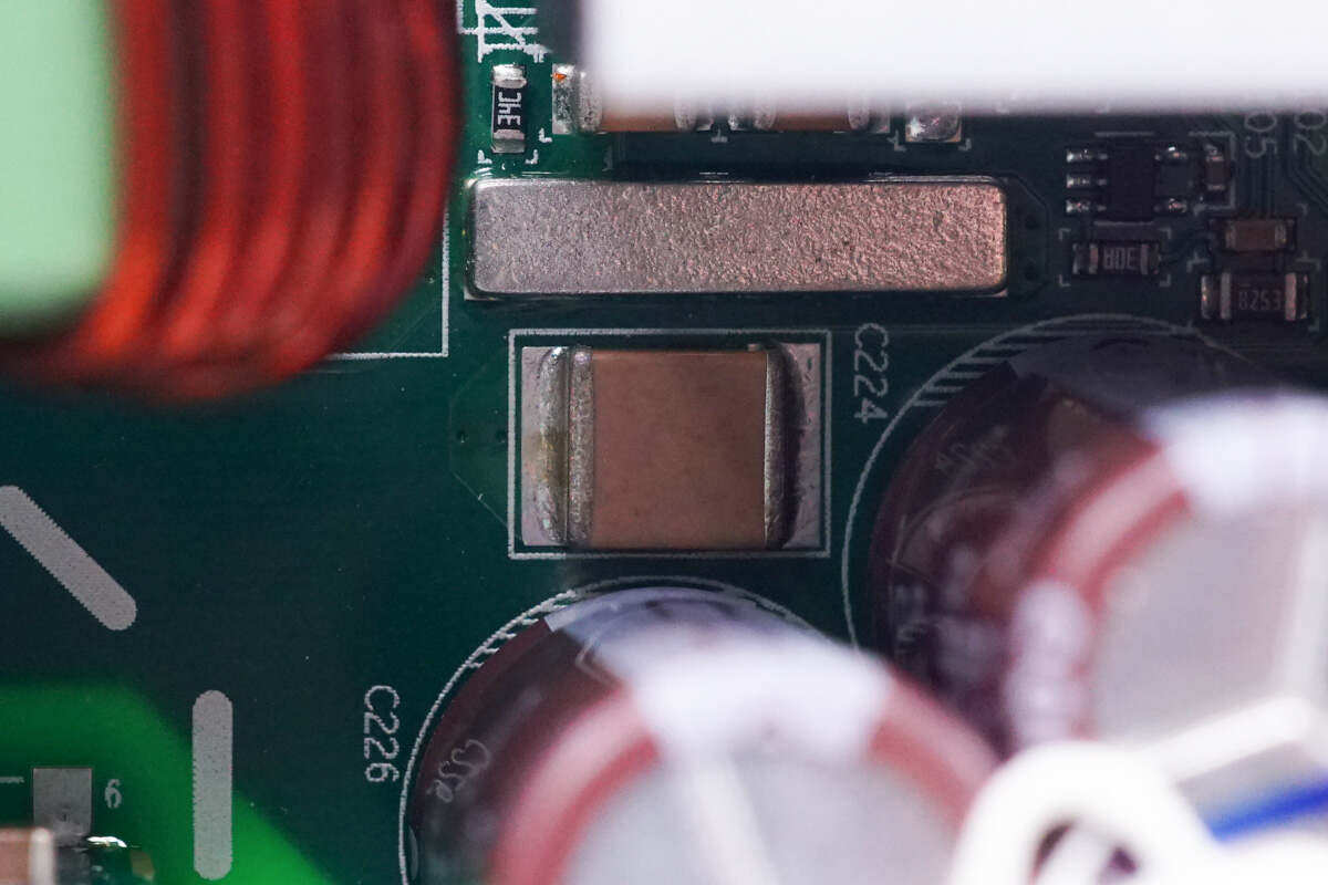
A 2220 encapsulated MLCC is used for output filtering.
The output filter inductance adopts magnetic ring winding, and bakelite board insulation is set in the middle and bottom.
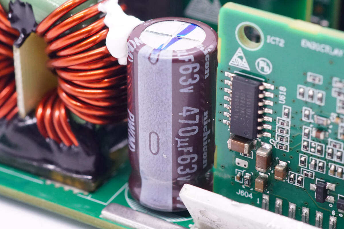
The output filter capacitor is from Nijikang, and the specification is 470μF63V。
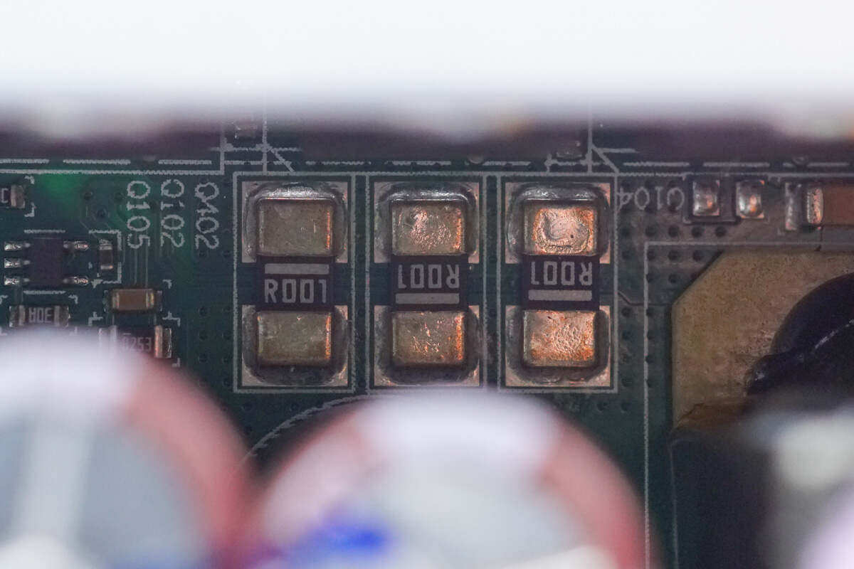
Three 1m Ω sampling resistors are used to detect the output current.
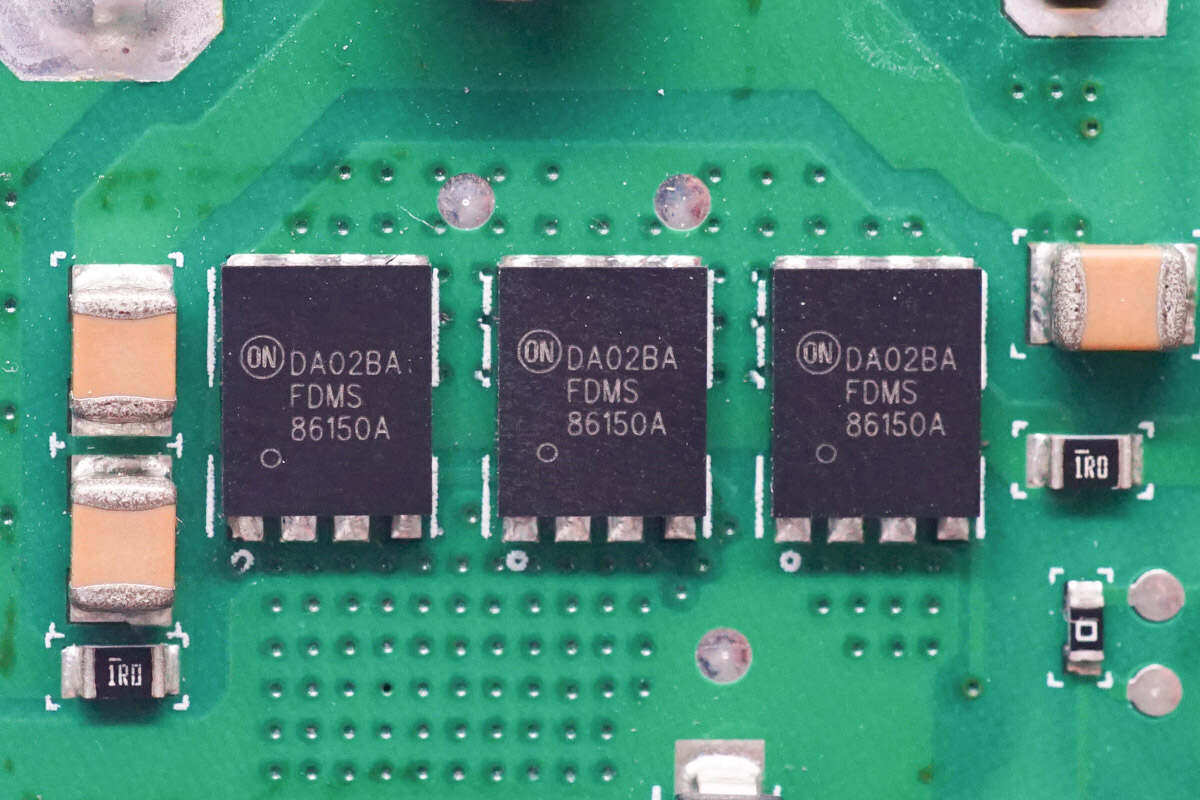
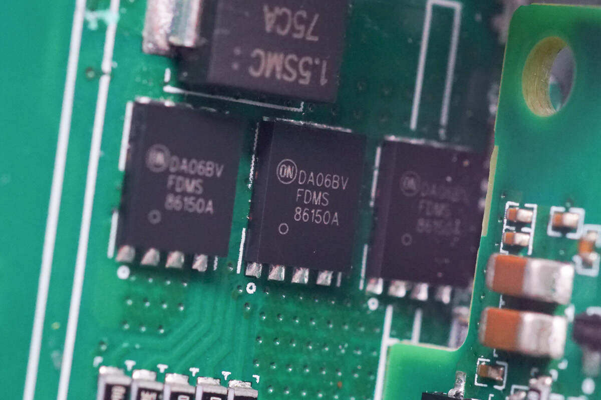
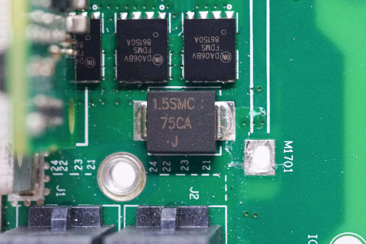
The output VBUS switch tube is from Ansomy, the model is FDMS86150A, NMOS, the withstand voltage is 100V, the resistance is 4.85m Ω, and it is packaged with Power 56.
Three VBUS switch tubes with the same model are welded on the front of PCBA module.
1.5SMC75CA TVS is used for output surge protection.
Close up of DC output socket of power module.
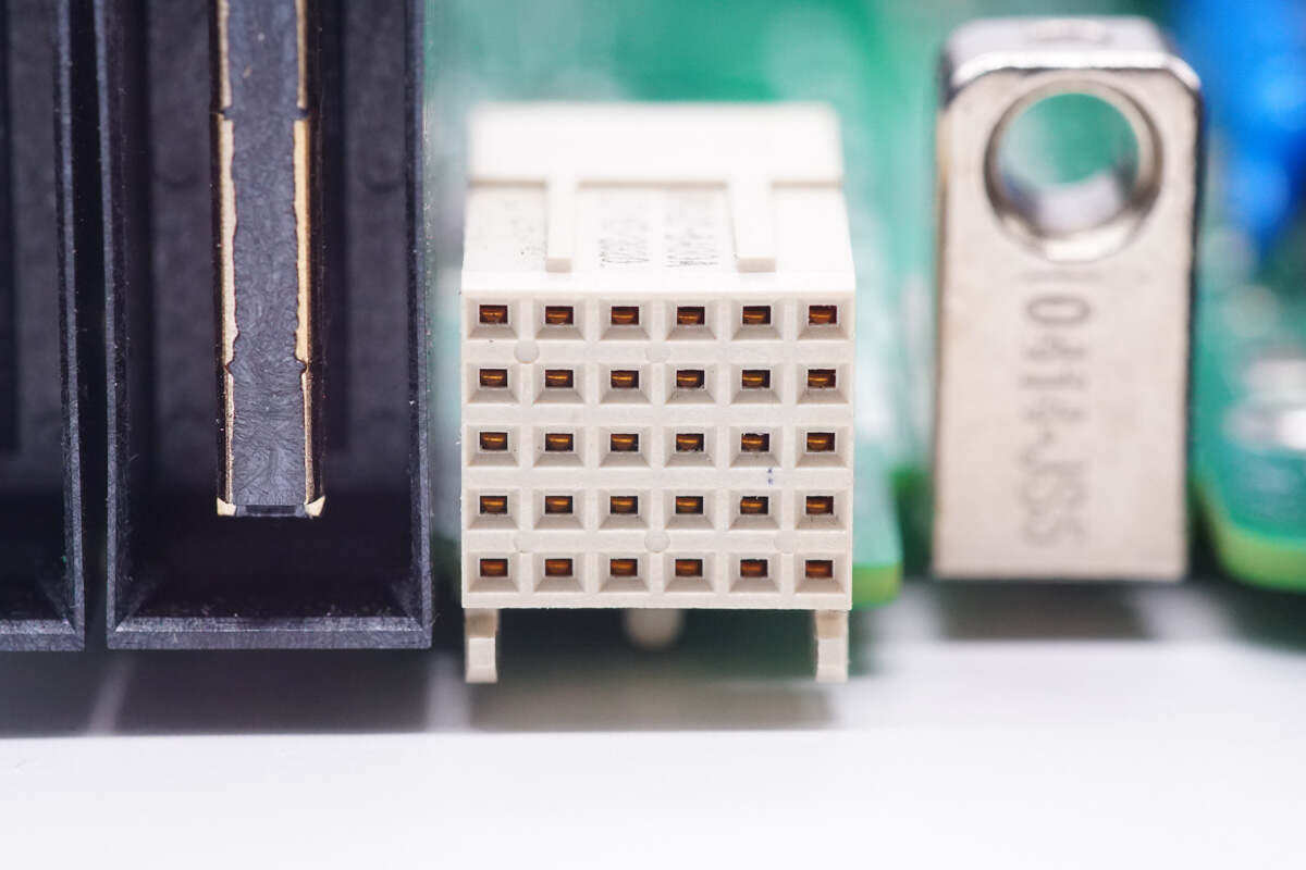
On the right side of the output socket is the power control socket, with a total of 30 pins.
There are several small boards on the input and output side of the PCBA module.
One of the small boards is insulated with a black plastic cover.
Remove the insulating plastic cover, and the inside is the auxiliary power panel.
Disassemble and remove three small boards. On the outside of the PCBA module is the main power control board.
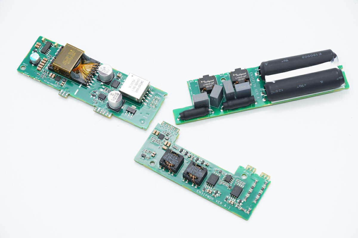
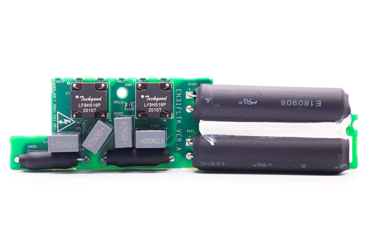
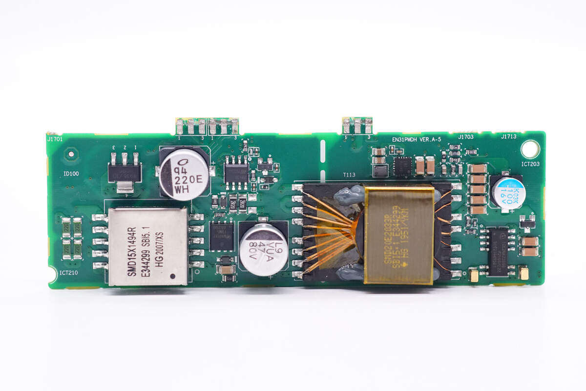
The three small boards are the auxiliary power supply board, the rectifier filter board and the isolation drive board below.
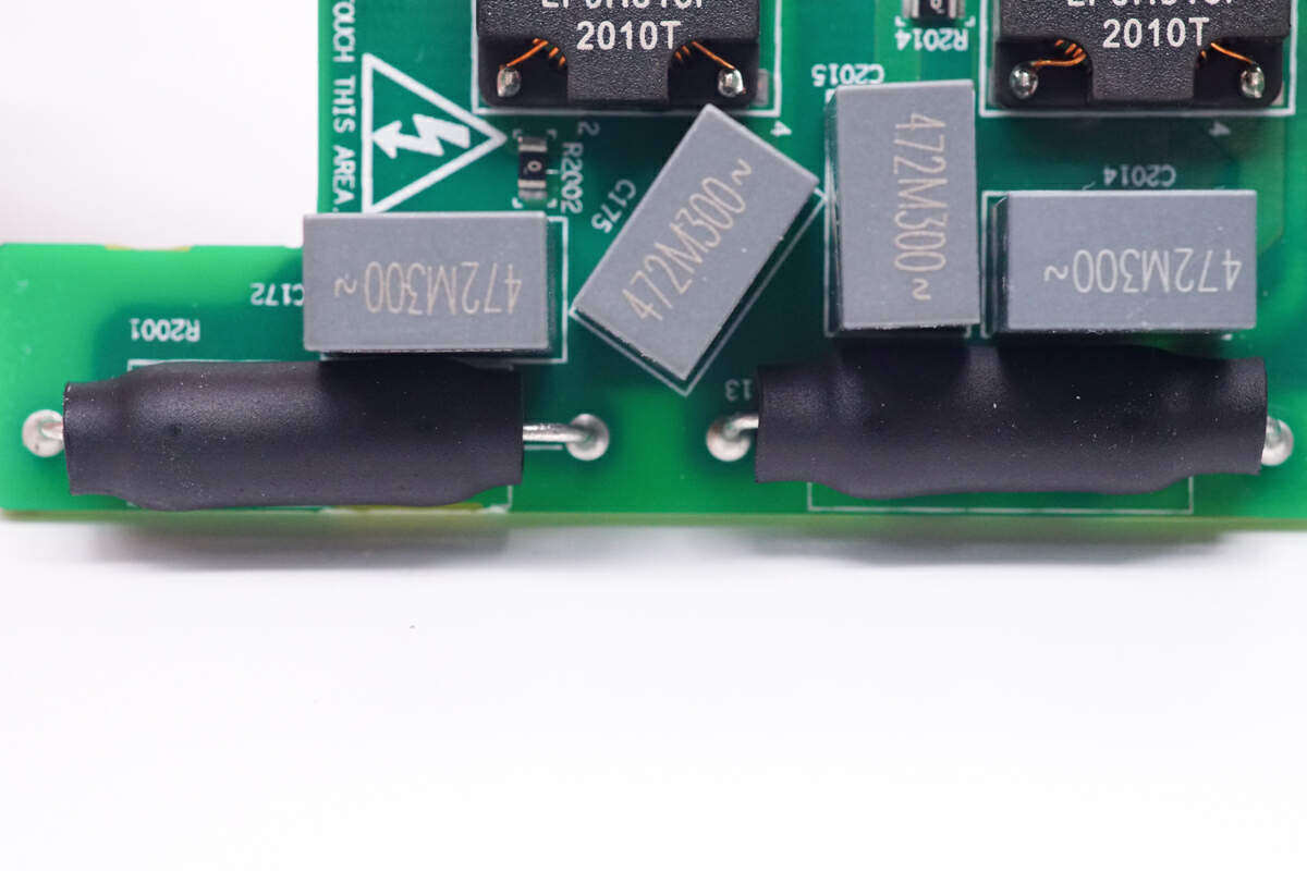
The front of the small rectifier filter board is welded with a common mode inductor and a film capacitor. The lower two resistors are sheathed with heat shrinkable tubes, and the right two electrolytic capacitors are also sheathed with heat shrinkable tubes.
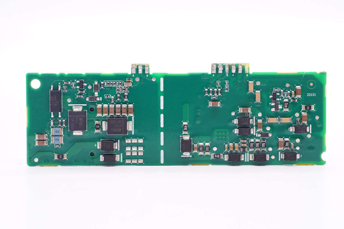
Eight patch diodes are welded on the back, and the corresponding position of the electrolytic capacitor is hollowed out to reduce the thickness.
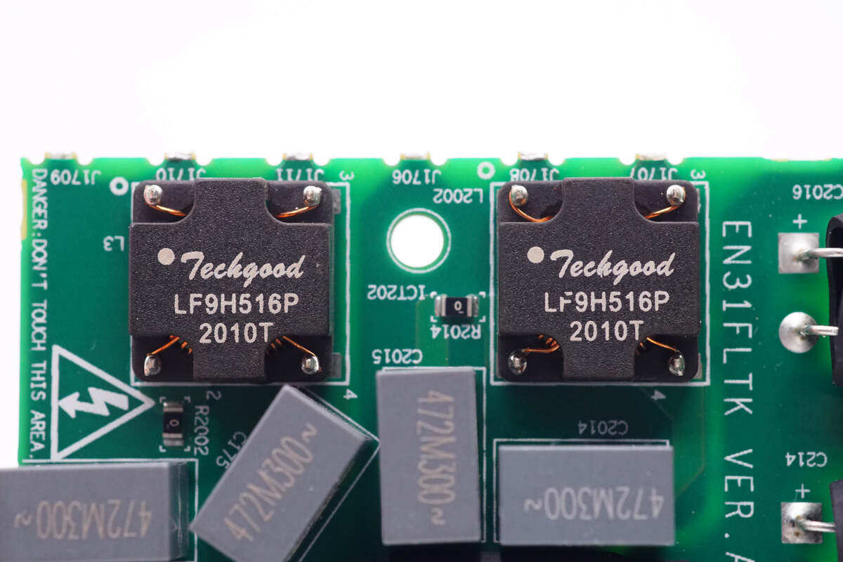
Two SMD common mode inductance silk screen LF9H516P.
The film capacitance is 0.0047μF. A total of four.
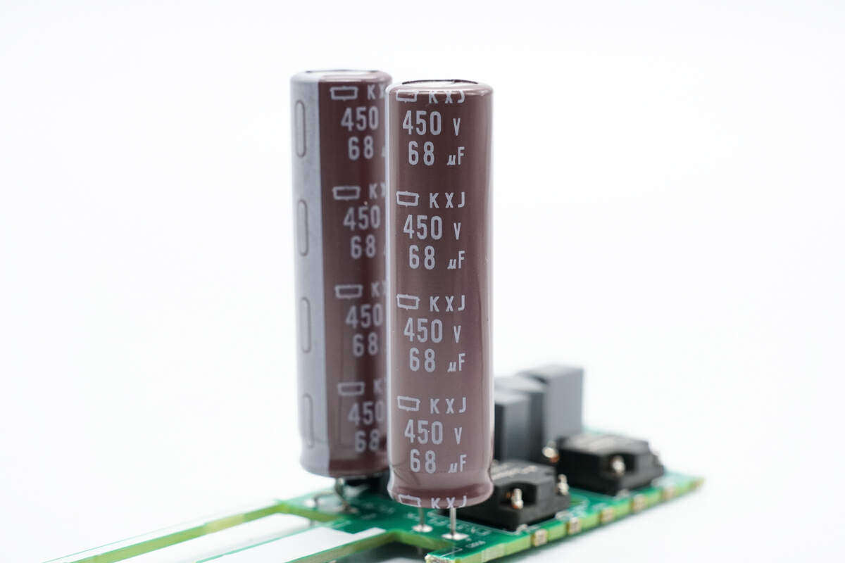
The two electrolytic capacitors are insulated with heat shrinkable tubes and fixed with glue.
Two filter capacitors from Guimigong, specification: 450V68μF。
The auxiliary power supply board is at a glance. The right side of the dotted line is the high-voltage side, and the left side is the low-voltage side. It is designed for two independent power supplies.
On the back of the small auxiliary power supply board, a rectifier diode, a filter capacitor and a feedback optocoupler are welded.
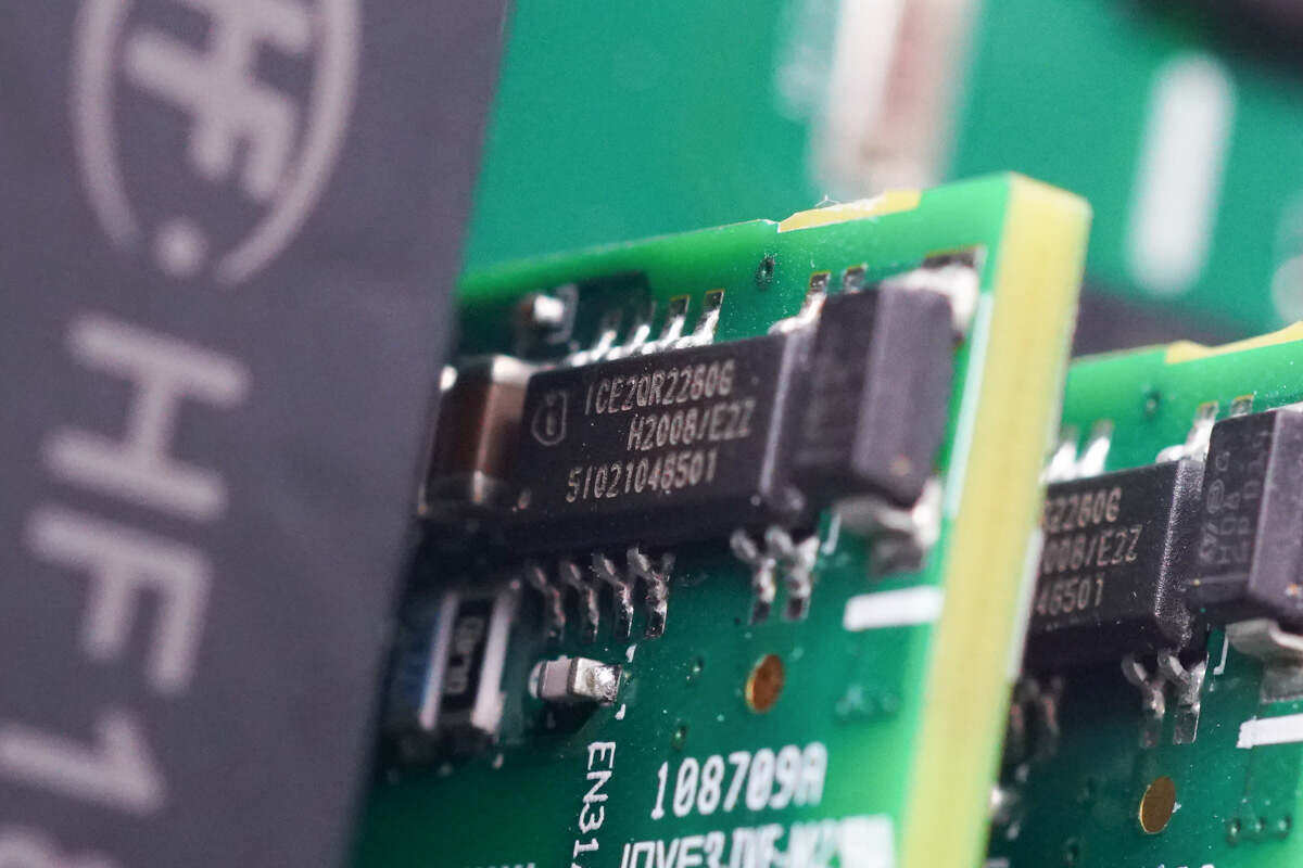
The auxiliary power supply chip is from Infineon, with the model of ICE2QR2280G. It is a power supply chip integrated with a switch tube, with 800V CoolMOS tube built-in. It supports 30W output power under 85-265Vac input.The chip has built-in cycle by cycle current limitation and turn back correction, and supports digital soft start and active burst mode.
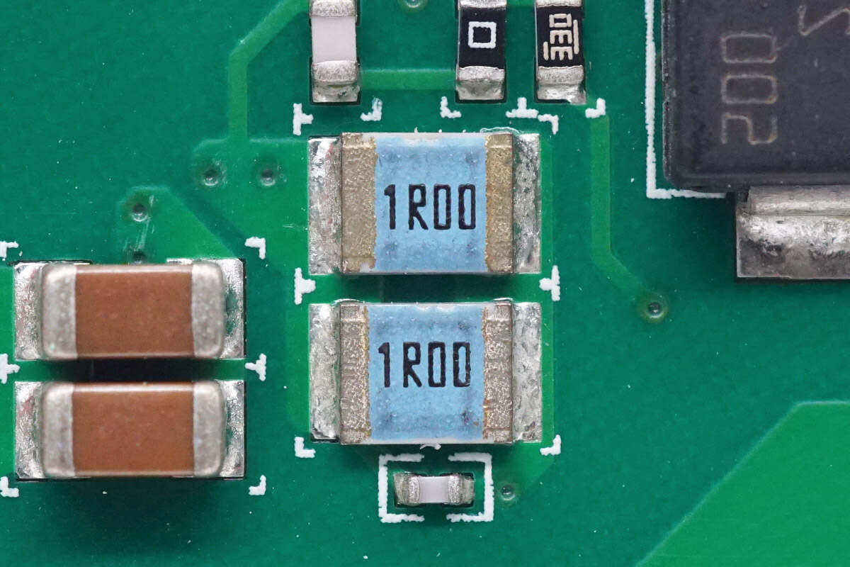
Two 1 Ω resistors are connected in parallel to detect the primary current.
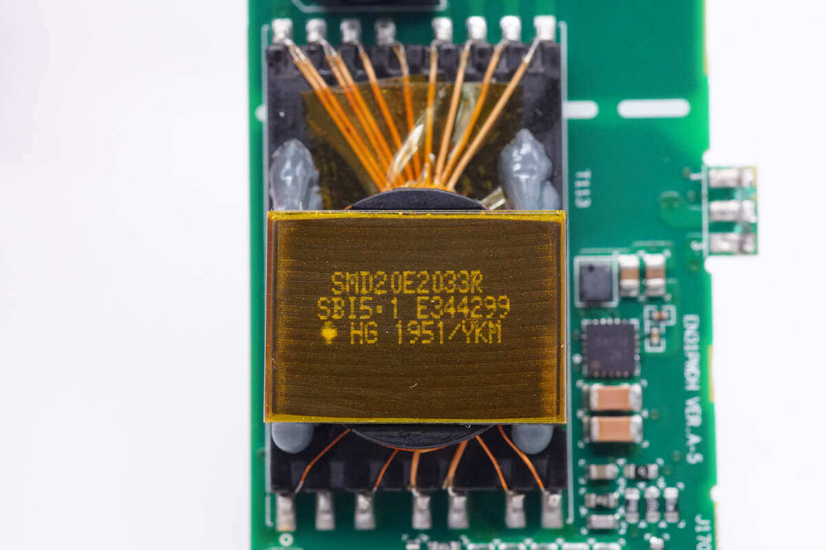
The power transformer is wound with multi-layer insulated wire, and the magnetic core is also wound with tape for insulation.
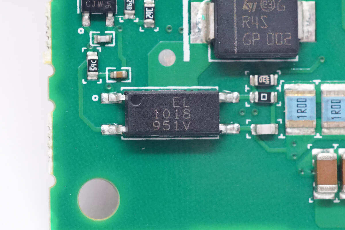
Yiguang EL1018 optocoupler is used for output voltage feedback.
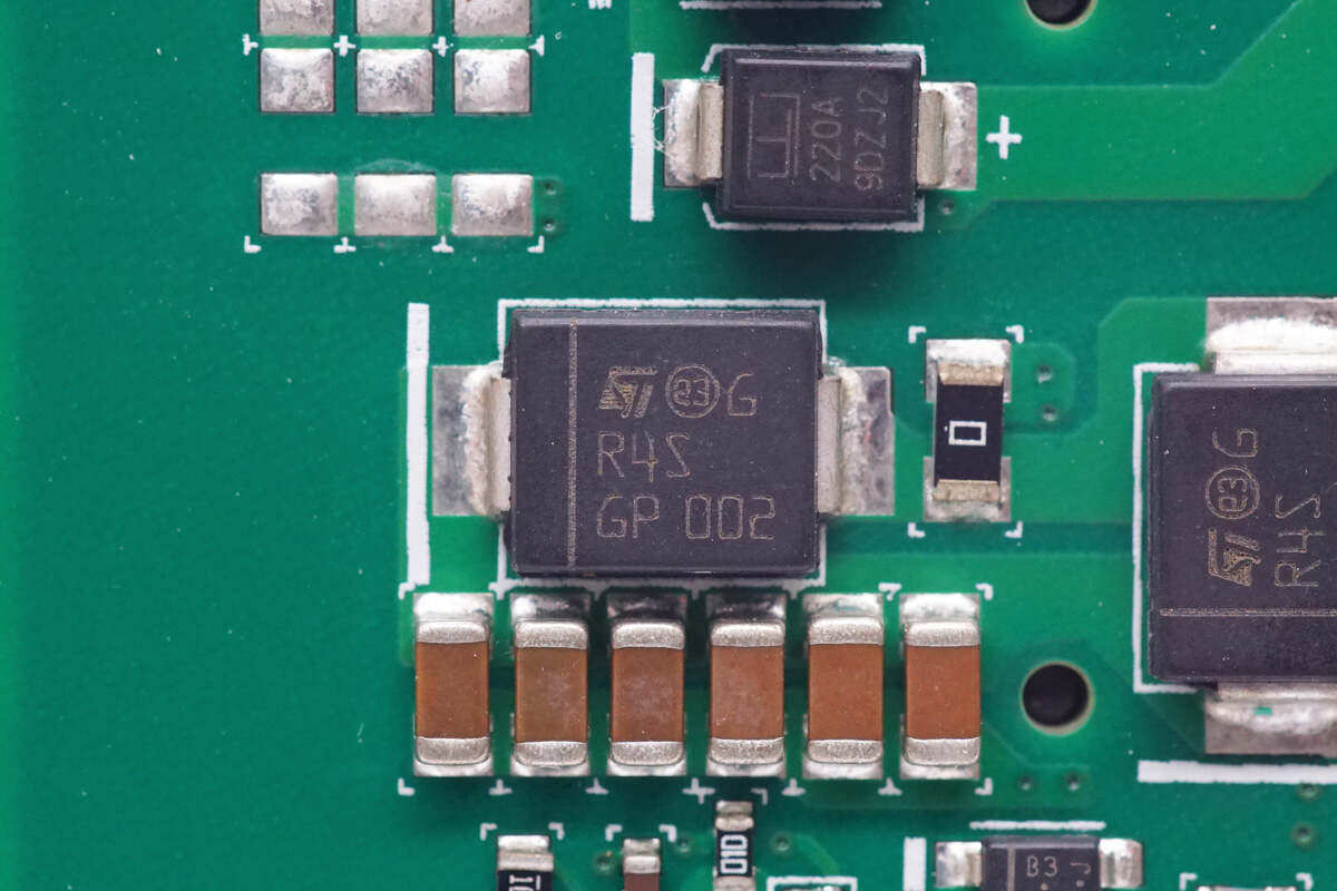
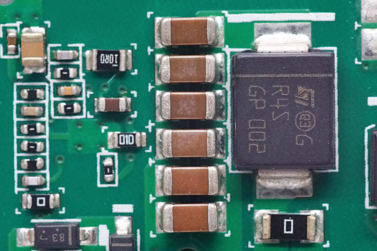
Rectifier diode from STC, screen printed R4S.
Close up of six MLCC filter capacitors in parallel.
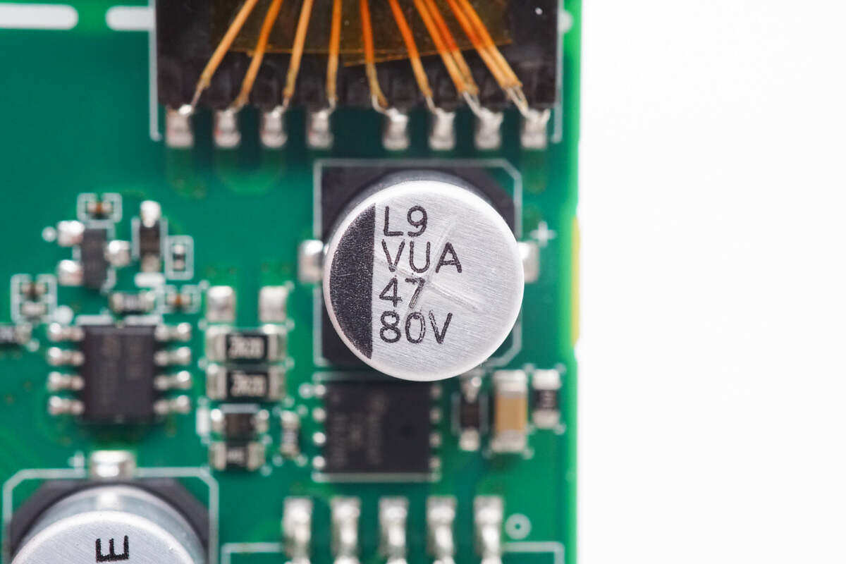
The specification of one filter capacitor is 47μF80V。
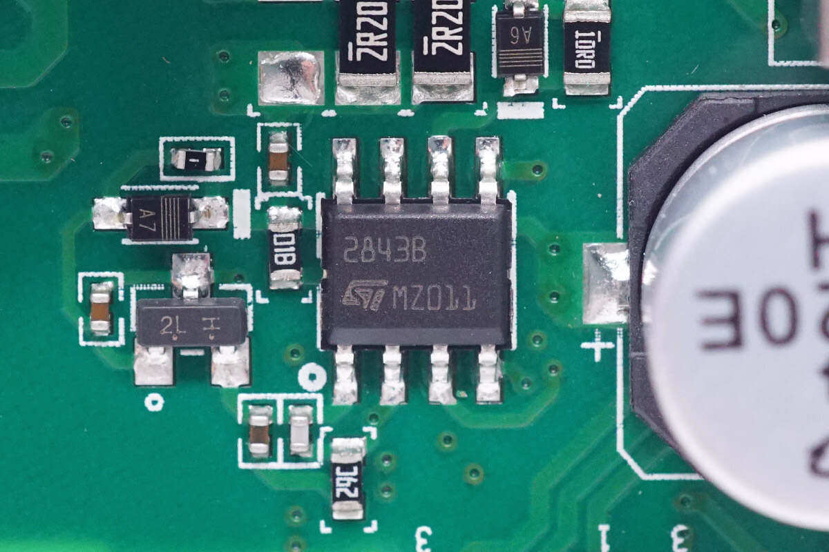
The main control chip of power supply adopts STC UC2843B, which is an industrial chip.
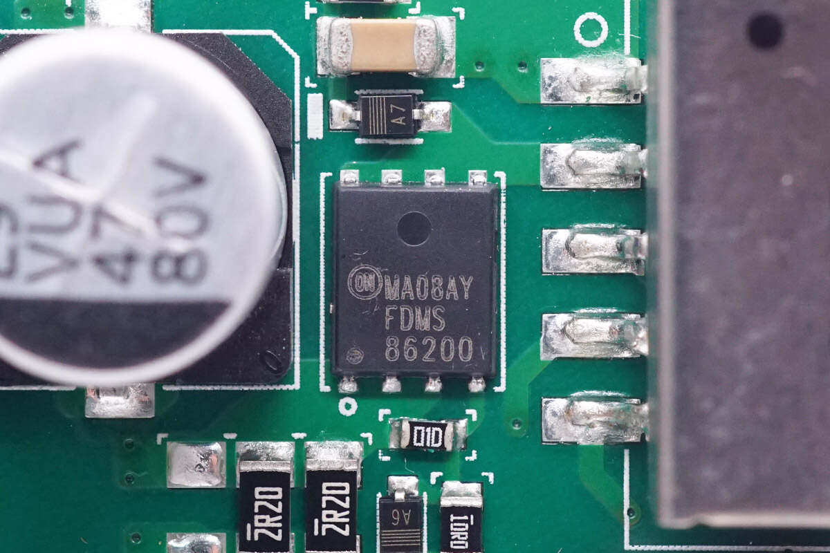
The switch tube adopts Ansomy FDMS86200, NMOS, withstand voltage of 150V, conductivity of 18m Ω, and Power56 packaging.
The transformer is covered with a metal shielding shell.
There are also two auxiliary power supply boards on the right side of the auxiliary power supply board.
The auxiliary power supply chip is from Infineon, model ICE2QR2280G.
Close up of planar transformer core.
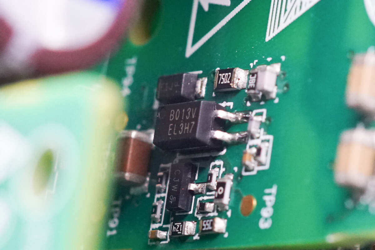
EL3H7 optocoupler is used for output voltage feedback.
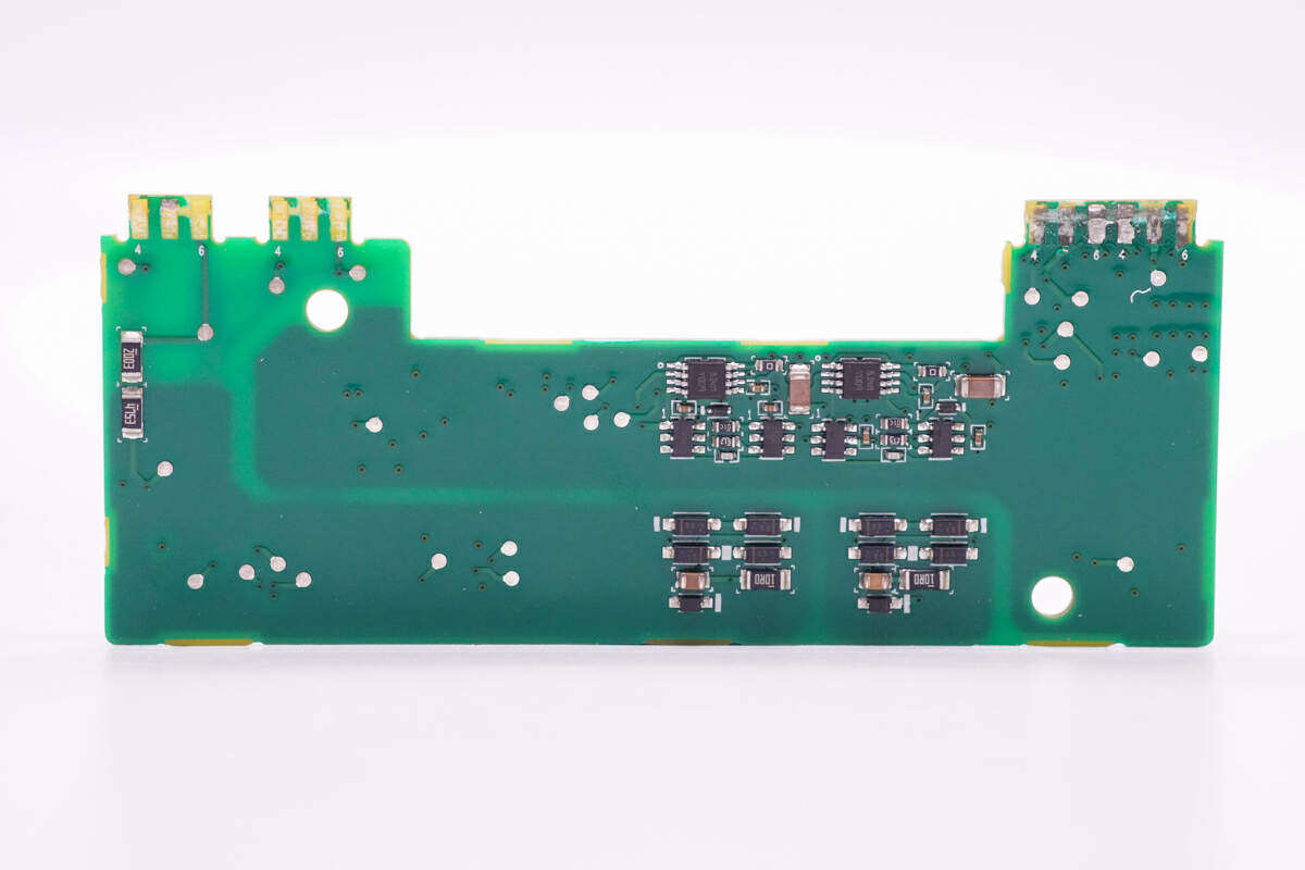
Close up of isolation drive board, front welding drive transformer and isolation amplifier.
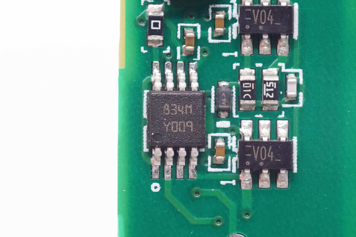
Two driver chips are soldered on the back.
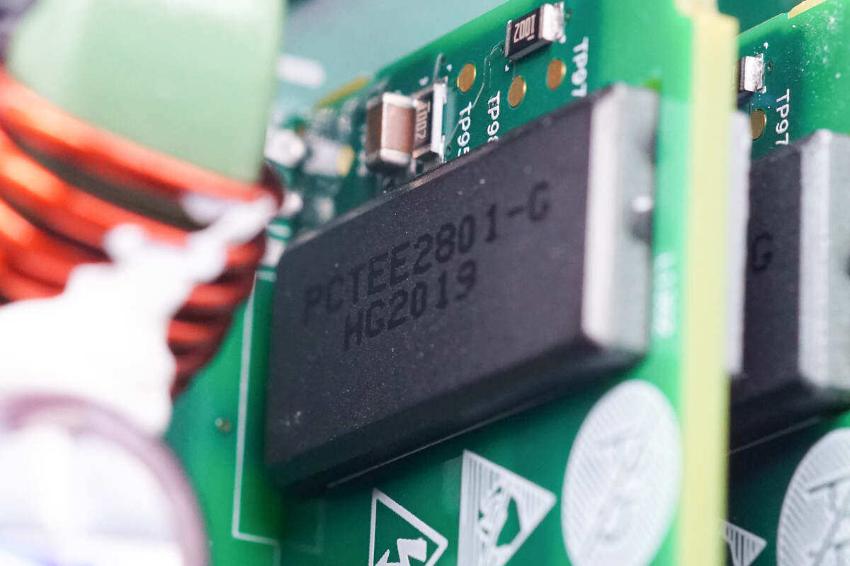
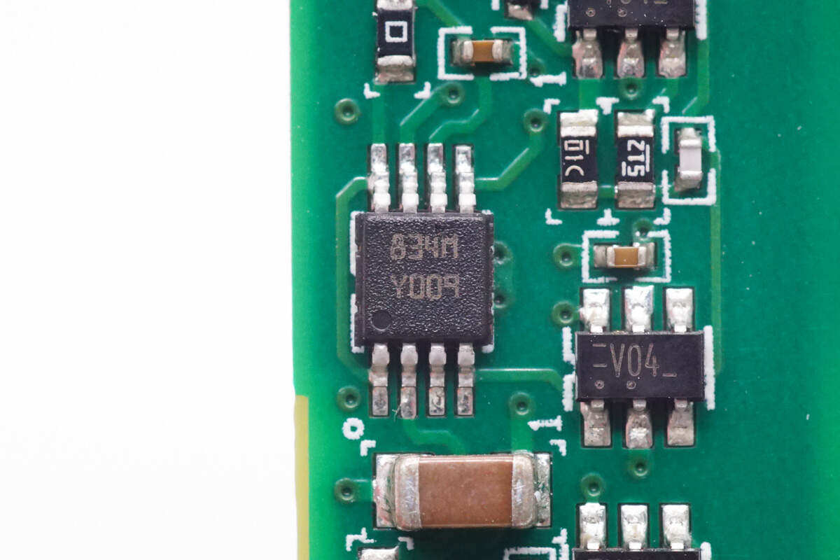
The driver chip, PM8834M, is from STMicroelectronics. It is a dual low side driver with 4A output capability and is packaged with MSOP 8L-EP.
The other drive is the same model.
Two isolating transformers are used for switching tube drive.
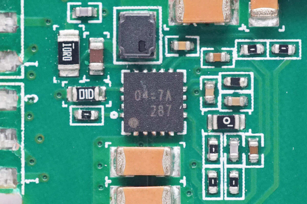
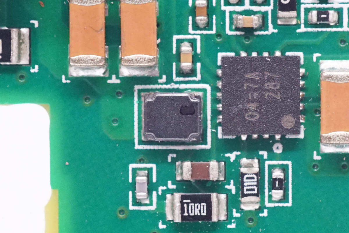
A power supply chip is screen printed 04=7A.
Close up of step-down inductance used together.
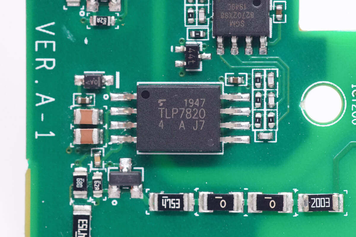
The optical isolation amplifier is from Toshiba, model TLP7820, which is suitable for motor current acquisition and inverter voltage and current acquisition.
The other optical isolation amplifier has the same model.
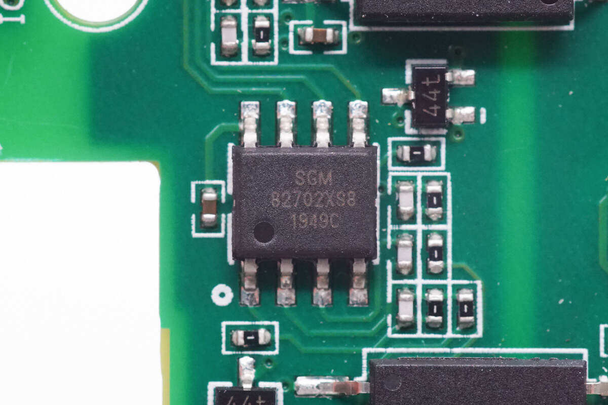
Simbond Micro SGM8270 dual operational amplifier is used for signal amplification.
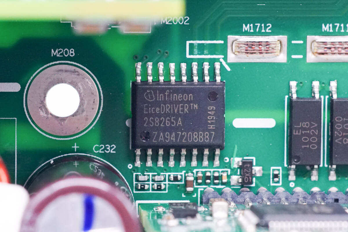
The isolation drive chip is from Infineon, model 2EDS8265H, EiceDRIVER 2EDi driver series, which is a fast dual channel isolation MOS tube drive chip with enhanced input and output isolation.
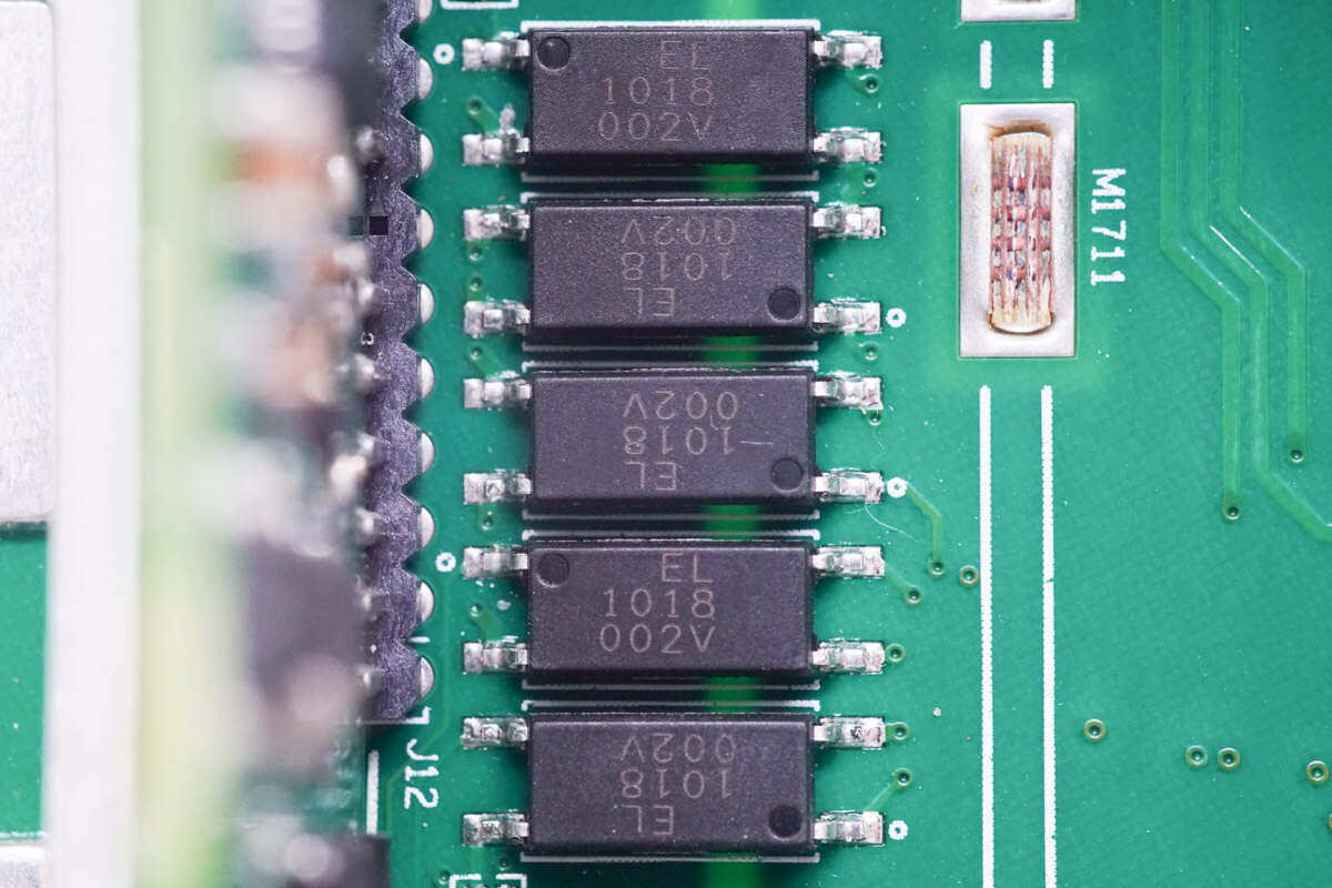
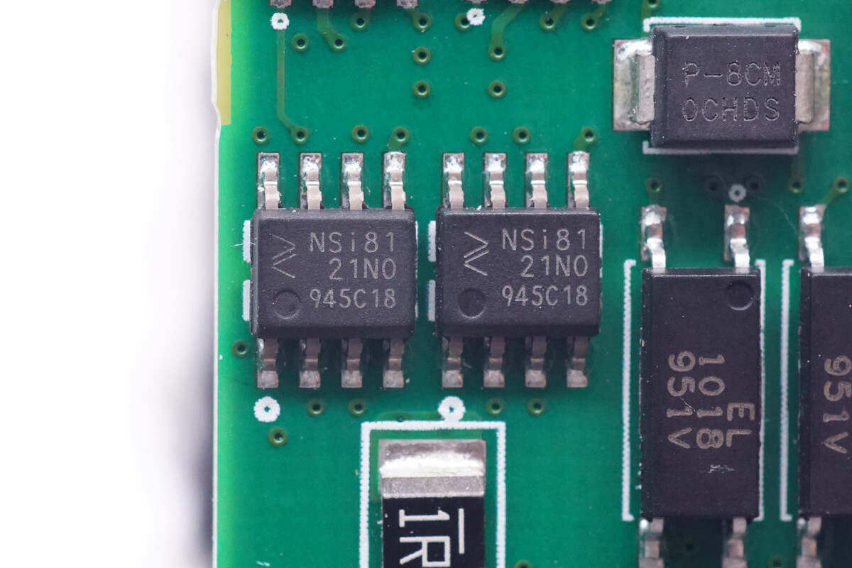
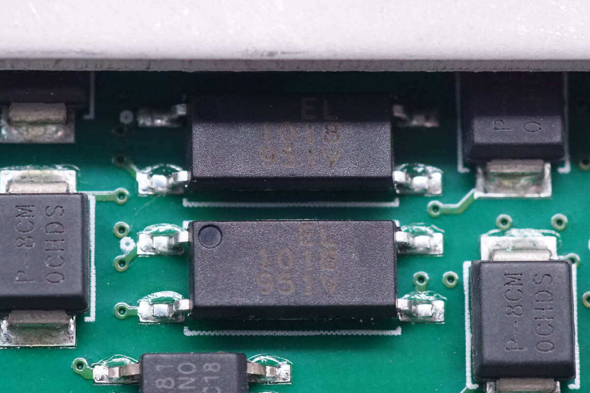
Five EL1018 optocouplers are used for communication between primary stages.
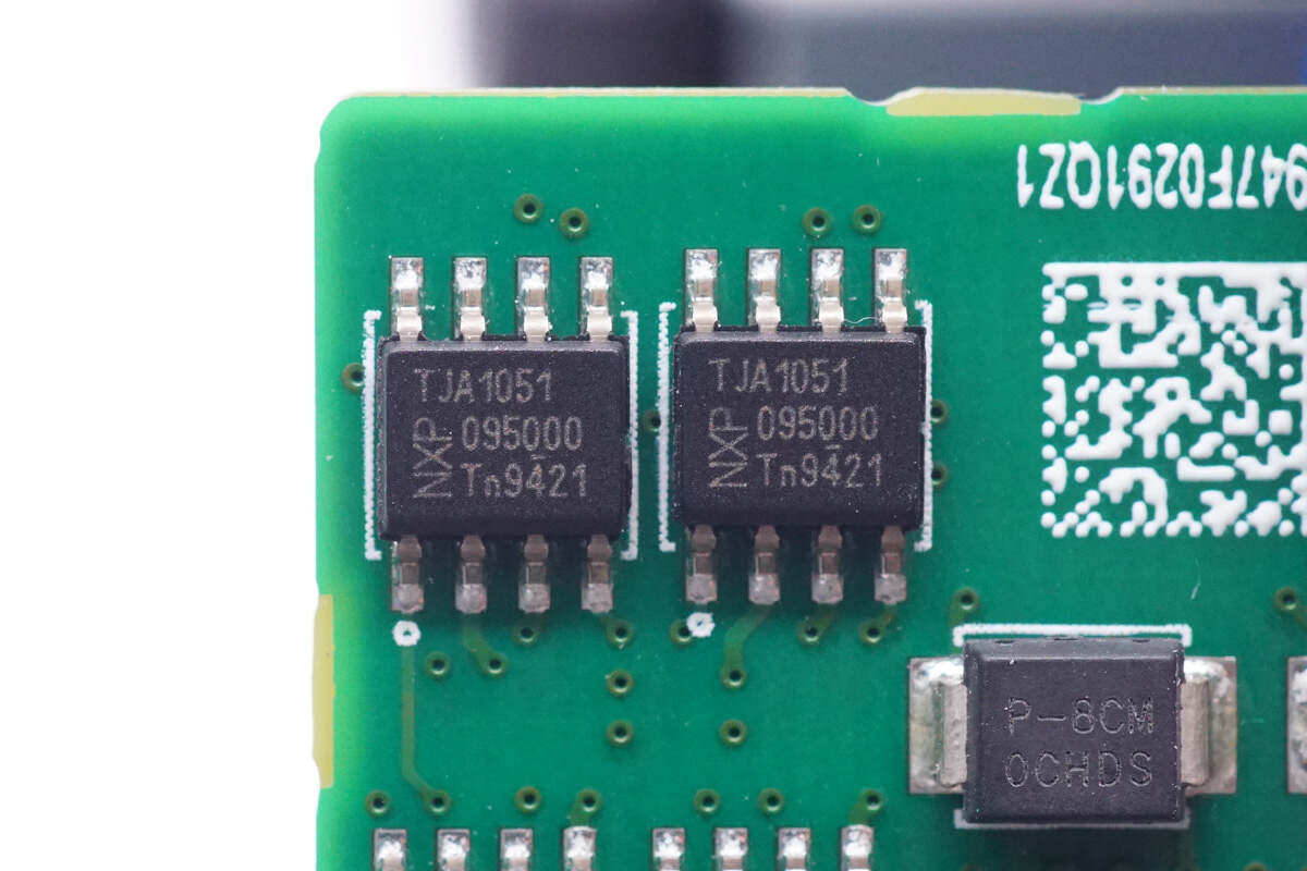
Weld two high-speed CAN transceivers from NXP (model: TJA1051) on the vertical panel at the side for communication between the power module and the host.
Two nano core micro NSi8121 dual channel digital isolators are used for communication isolation.
Two hundred million light EL1018 optocouplers are used for isolated communication.
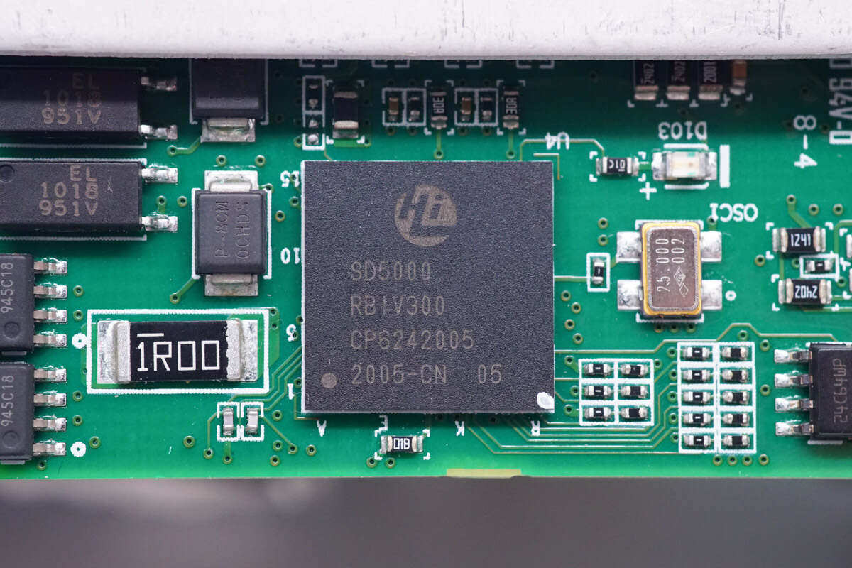
The secondary control chip is from HiSilicon Semiconductor and screen printed SD5000.
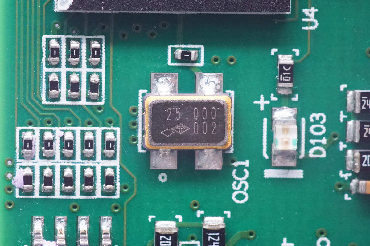
25.000MHz clock crystal oscillator is installed outside the chip.
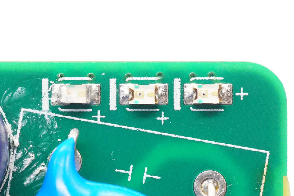
Close up of chip LED indicator.
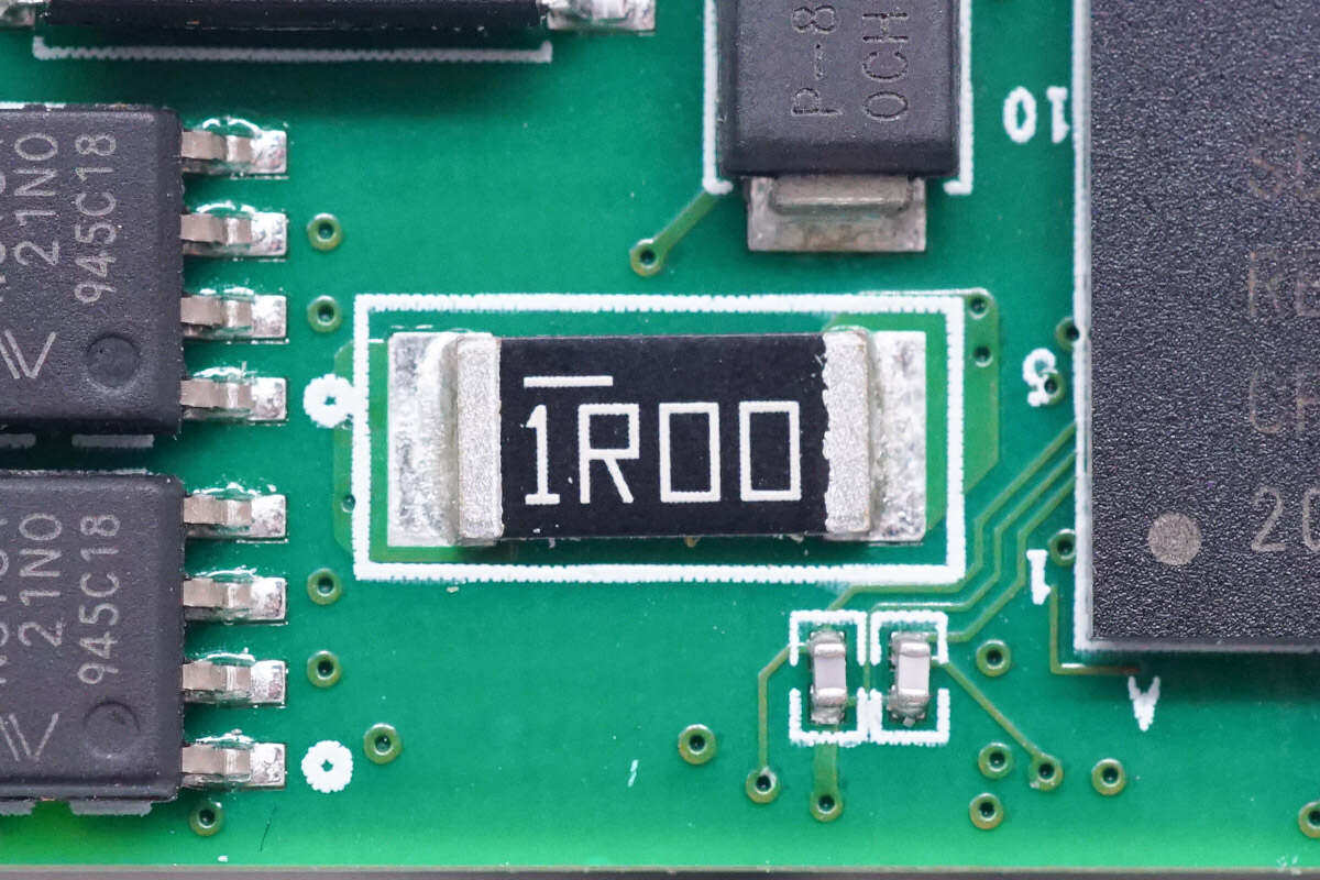
A 1 Ω patch resistor is welded on the left side of the chip.
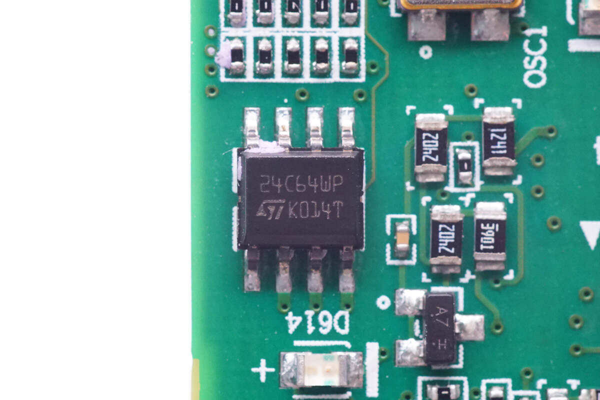
External memory from STC, model 24C64WP
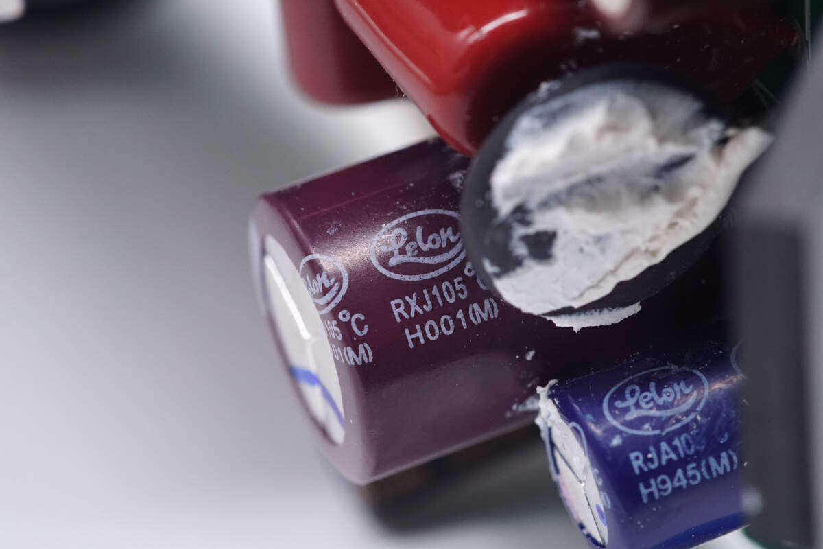
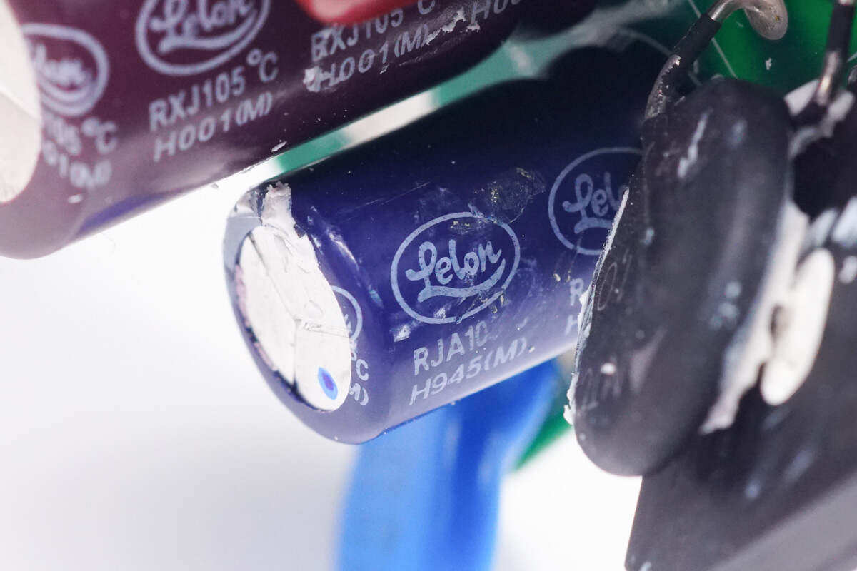
The electrolytic capacitor on the main board is from Lilong.
470μF100V。
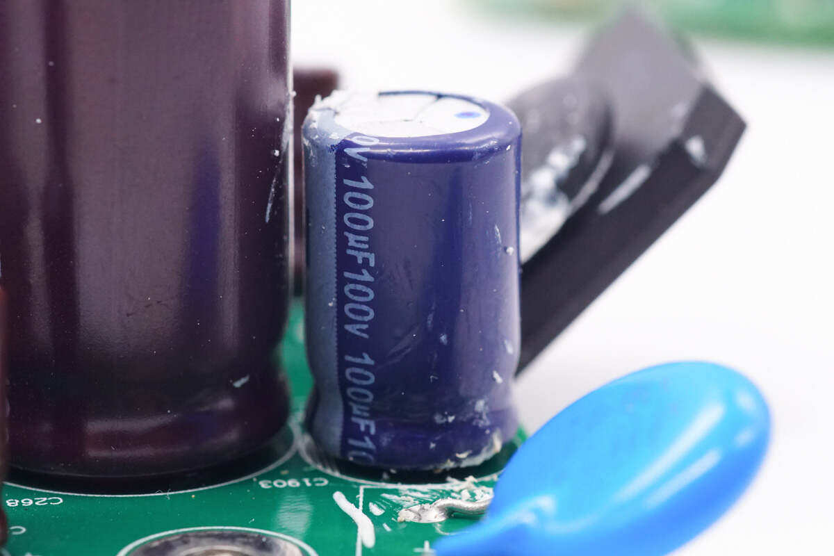
The electrolytic capacitor is also from Lilong.
Specification is 100μF100V。
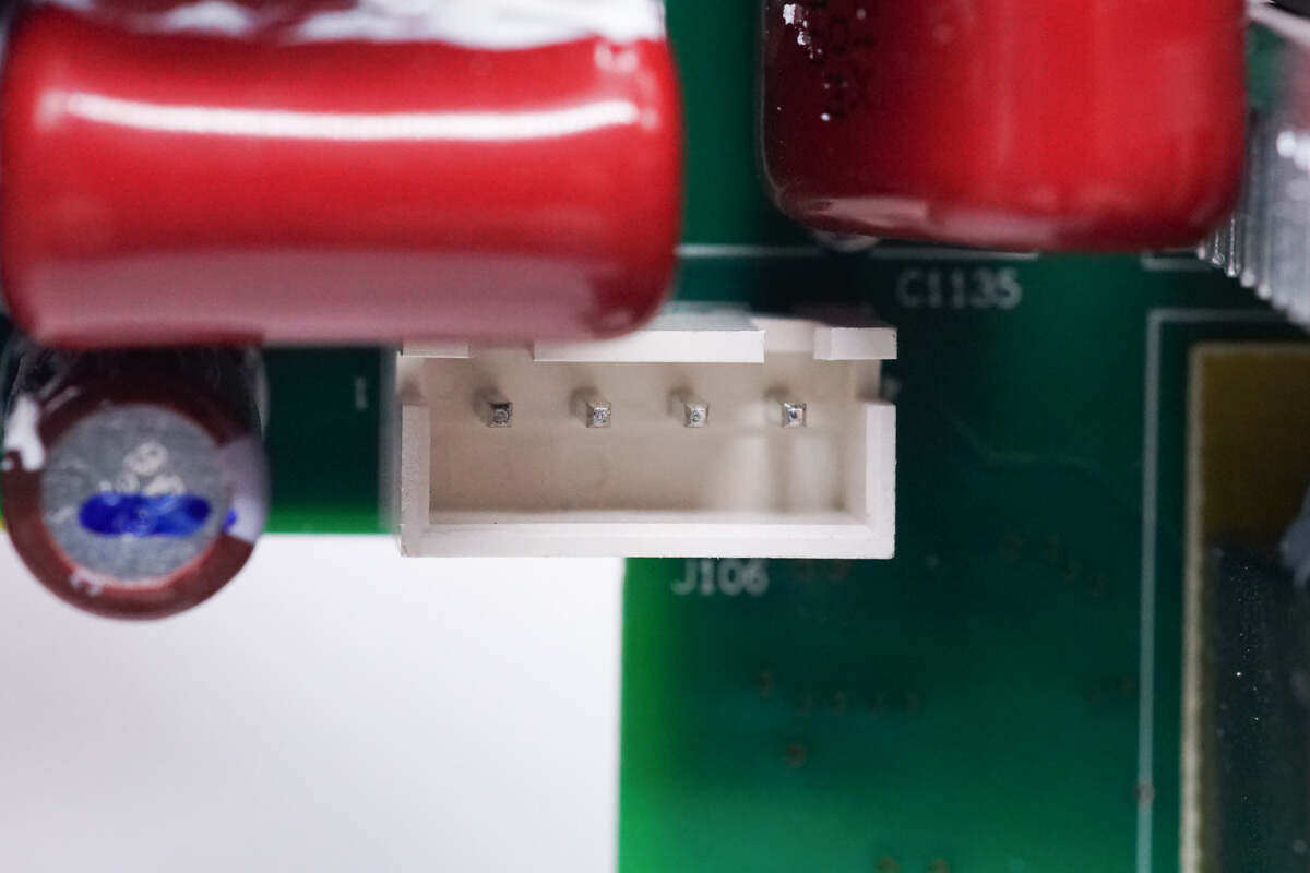
Close up of the socket used to connect the cooling fan.
Close up of three working indicators.
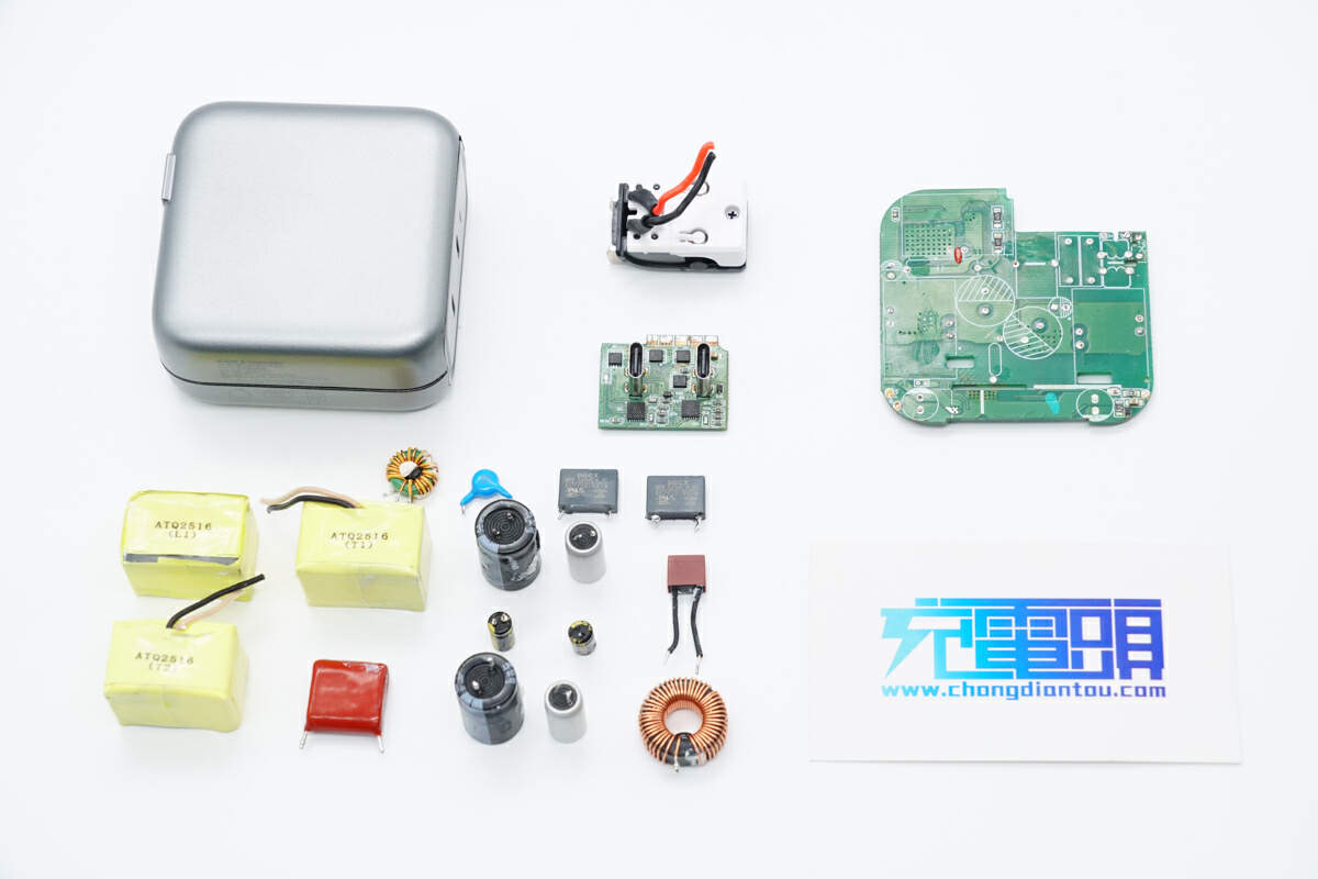
Take a look at all of them and have a family photo.
Disassembly summary of charging head network
The overall design of Huawei PAH-3000WA power module is modular. The front end of the power module is equipped with a cooling fan and an indicator light, and the rear of the module is equipped with input and output sockets and communication connectors to facilitate overall replacement.The module output specification is 53.5V 56.1A, and the calculated output power is 3000W.
The charging head network learned through disassembly that the AC input terminal of Huawei's power module is equipped with a fuse for overcurrent protection, and is equipped with a varistor and a gas discharge tube for surge protection.The module is controlled by Italian MCU. PFC switch tube and main switch tube are from Toshiba, PFC rectifier tube is from Kyocera, and synchronous rectifier tube and auxiliary power supply chip are from Infineon.
Several small boards are set inside the power module for auxiliary power supply and function control to save space.The internal main capacitor is from EPCOS and Guimigong, the output filter capacitor is from Nijikang, and the internal components are glued and reinforced.The overall materials are well-known brands, and the internal workmanship is solid and reliable.