Uploaded on: 2023-12-26 11:55:06 come from: Construction documents
zero
5 points

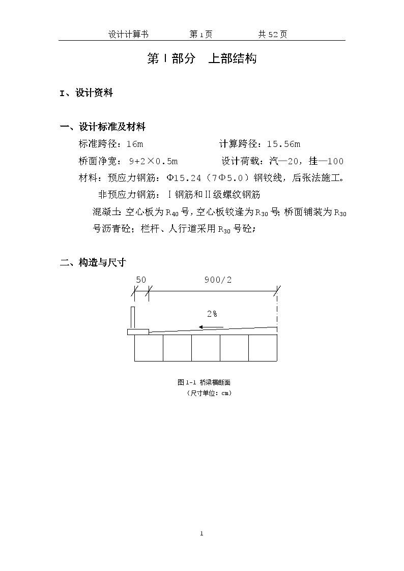
 Design Calculation Sheet of Post tensioned Prestressed Concrete Hollow Slab Bridge. doc - Figure 1

Design Calculation Sheet of Post tensioned Prestressed Concrete Hollow Slab Bridge. doc - Figure 1

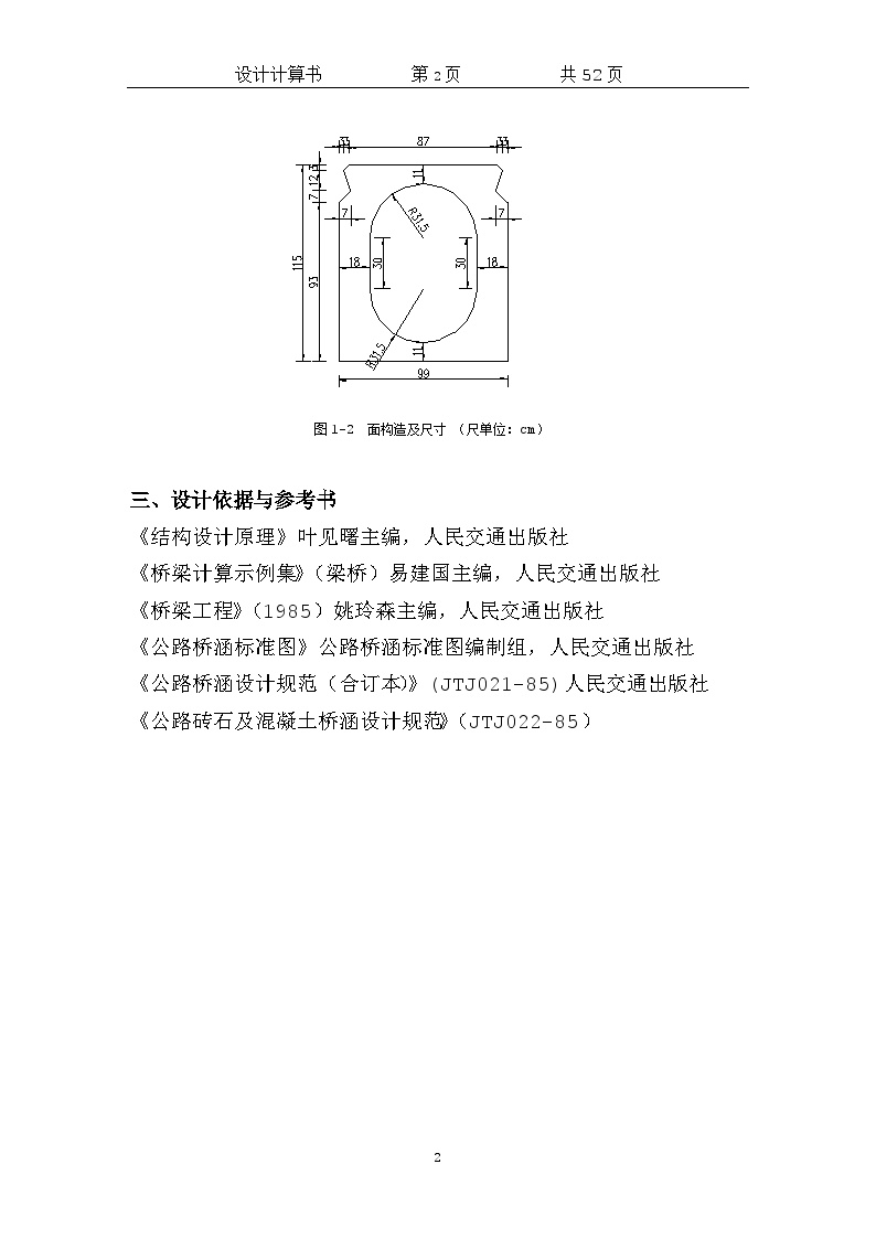
 Design Calculation Sheet of Post tensioned Prestressed Concrete Hollow Slab Bridge. doc - Figure 2

Design Calculation Sheet of Post tensioned Prestressed Concrete Hollow Slab Bridge. doc - Figure 2

 Design Calculation Sheet of Post tensioned Prestressed Concrete Hollow Slab Bridge. doc - Figure 3

Design Calculation Sheet of Post tensioned Prestressed Concrete Hollow Slab Bridge. doc - Figure 3

 Design Calculation Sheet of Post tensioned Prestressed Concrete Hollow Slab Bridge. doc - Figure 4

Design Calculation Sheet of Post tensioned Prestressed Concrete Hollow Slab Bridge. doc - Figure 4

 Design Calculation Sheet of Post tensioned Prestressed Concrete Hollow Slab Bridge. doc - Figure 5

Design Calculation Sheet of Post tensioned Prestressed Concrete Hollow Slab Bridge. doc - Figure 5

Click to download the source file now

Special statement: This material belongs to the sharing uploaded by users Downloaded content, only for learning, not for commercial use. If there is any copyright problem, please timely contact Station delete!

Collection
share

WeChat code scanning and sharing

Click to share

  • Detail Design of Continuous Joints of 20m Pretensioned Prestressed Concrete Hollow Slab Deck

    2. The upper structure adopts pretensioned prestressed concrete hollow slab, the lower pier adopts thin-walled pier and expanded foundation, and the abutment adopts U-shaped abutment and expanded foundation. 3. The bearing capacity of pier and abutment base is 350KPa. 4. The bridge deck is paved with 6~10cm asphalt concrete+10cm # 50 waterproof concrete. 5. The bridge is equipped with a WABO Wanbao embedded expansion device at abutment 0 and abutment 2 respectively.   

  • Design of 20m pretensioned prestressed concrete simply supported hollow slab
    1) Design load The design load level of this bridge is determined as vehicle load (highway level II), and the crowd load is 3.5KN/m2 (2) Bridge deck span and clear width Standard span: Lk=20m Calculated span: L=19.50 m Clear width of bridge deck: 15+2 × 1.5m Total length of main beam: 19.96m.
  • Design drawing of pretensioned prestressed concrete hollow slab of a highway

    In this drawing, the standard spans are 10m, 13m, 16m and 20m. General drawing of pretensioned prestressed concrete hollow slab. I. Description of superstructure of prestressed concrete hollow slab (L=10, 13, 16, 20m, a=0~45 °) Quantity table of main materials for L=10m hollow slab and one hole superstructure, cross-section drawing of superstructure, general structural drawing of precast slab, layout drawing of middle slab reinforcement, quantity table of middle slab materials, layout drawing of side slab reinforcement, quantity table of side slab materials, layout drawing of cast-in-situ layer reinforcement of bridge deck, layout drawing of obtuse angle reinforcement of inclined slab deck, structural drawing of embedded steel plate of support Quantity table of main materials for one hole superstructure of L=13m hollow slab, cross-section drawing of superstructure, general structural drawing of precast slab, layout drawing of middle slab reinforcement, quantity table of middle slab materials, layout drawing of side slab reinforcement, quantity table of side slab materials, layout drawing of cast-in-situ layer reinforcement of bridge deck, layout drawing of obtuse angle reinforcement of inclined slab deck, structural drawing of embedded steel plate of support Quantity table of main materials for upper structure of one hole of L=16m hollow slab, cross-section drawing of upper structure, general structural drawing of precast slab, layout drawing of reinforcement for medium slab, quantity table of material for medium slab, layout drawing of reinforcement for side slab, quantity table of material for side slab, layout drawing of reinforcement for cast-in-situ layer of bridge deck, layout drawing of reinforcement for obtuse angle slab of inclined slab, structural drawing of embedded steel plate of support Quantity table of main materials for one hole superstructure of L=20m hollow slab, cross-section drawing of superstructure, general structural drawing of precast slab, layout drawing of middle slab reinforcement, quantity table of middle slab materials, layout drawing of side slab reinforcement, quantity table of slab materials, layout drawing of cast-in-situ layer reinforcement of bridge deck, layout drawing of obtuse angle reinforcement of inclined slab deck, structural drawing of embedded steel plate of support II Description of substructure drawing of prestressed concrete hollow slab (pier L=10, 13, 16, 20m, a=0 °~ 45 °), general structural drawing of pile column pier (a=0 °~ 45 °), structural drawing of pier cap reinforcement (L=10m; a=0 °~ 45 °), quantity table of pier cap materials (L=10m; a=0 °~ 45 °), structural drawing of pier cap reinforcement (L=13m; a=0 °~ 45 °); A=0 °~ 45 °) Pier Cap Material Quantity Table (L=13m; a=0 °~ 45 °) Pier Cap Reinforcement Structural Drawing (L=16m; a=0 °~ 45 °) Pier Cap Material Quantity Table (L=16m; a=0 °~ 45 °) Pier Cap Reinforcement Structural Drawing (L=20m; a=0 °~ 45 °) Pier Cap Material Quantity Table (L=20m; a=0 °~ 45 °); A=0 °~ 45 °) Structural drawing of pier anchor bolt III Structural drawing of lower part of prestressed concrete hollow slab (abutment L=10, 13, 16, 20m, a=0 °~ 45 °) Description General structural drawing of pile column abutment (a=0 °~ 45 °) Structural drawing of abutment cap reinforcement (L=10m; a=0 °~ 45 °)

  • Construction of precast pretensioned prestressed concrete hollow slab beam
    Content introduction According to the quantity and schedule of pretensioned prestressed concrete hollow slabs in this bid section, it is planned to set up a 5-slot long line tensioning pedestal, and each slot can prefabricate 3 pieces of hollow slab beams at the same time. When the prestress is applied, the initial stress is tensioned individually, and then the overall tension is applied. In order to speed up the progress, the concrete is mixed with high-efficiency water reducer, and steam curing is used in low temperature season to improve the early strength of concrete. The external formwork is made of steel, and the internal formwork is made of rubber air bags. The construction method is as follows: (1) Build a bridge factory. To achieve "three supplies and one leveling", that is, water supply, electricity supply, road access and site leveling. ① The ground where the pedestal is located shall be leveled and compacted, and then the slotting construction shall be carried out. The pedestal shall be provided with a long line reinforced concrete dowel column structure. The dowel column shall be provided with ground beams at a certain distance in the longitudinal direction, and end zone columns at the end to increase the anti overturning and anti sliding capacity. The pedestal bottom plate shall be made of terrazzo as the template, and angle steel shall be embedded at both sides to accurately fix the bottom width of the beam body and prevent the damage of the corner concrete. ② Tension beams are set at both ends of the pedestal, and prestressed anchor plates are set on the beams. ③ A pair of ground anchor rings shall be embedded every 0.5m on both sides of the pedestal to tension the side formwork. (2) Processing of steel bars and steel strands ① Steel bars and steel strands shall be provided with factory quality certificates and test reports, and shall be subject to sampling inspection at the frequency required by the specification. Steel bars and steel strands shall be stacked with tags according to different specifications. In order to avoid rust and pollution, steel bars and steel strands shall be stacked in a special reinforcement shed. ② The bottom plate and web reinforcement can be pre processed into a reinforcement skeleton according to the design drawing, and the top plate reinforcement can be processed into another skeleton. In order to strengthen the integrity and firmness of the reinforcement skeleton, spot welding shall be carried out at necessary positions. After the reinforcement skeleton is processed, the size, quantity and welding quality of the reinforcement shall be carefully checked.
  • Complete set of construction drawings of 1 × 13m pretensioned prestressed concrete hollow slab bridge

    Data Catalog Design Description Bill of Quantities Bridge Site Plan Bridge General Layout Bridge Cross Section and Hinge Joint Reinforcement Structural Drawing Hollow Slab General Structural Drawing Middle Slab Reinforcement Structural Drawing (I) Middle Slab Reinforcement Structural Drawing (II) Side Slab Reinforcement Structural Drawing (I) Side Slab Reinforcement Structural Drawing (II) Structural Drawing of Reinforcement for Deck Pavement Structural Drawing of Bearing and Anti seismic Anchor Bolt Structural Drawing of Continuous Reinforcement for Deck Structural Drawing of Expansion Joint Structural Drawing of Reinforcement for Guardrail Structural Drawing of Drainage Pipe Structural Drawing of General Structural Drawing of Abutment Structural Drawing of Reinforcement for Abutment Capping Beam Structural Drawing of Reinforcement for Abutment Retaining Block Structural Drawing of Reinforcement for Abutment Ear Wall Structural Drawing of Reinforcement for Abutment Pile Foundation Structural Drawing of Reinforcement for Abutment Approach Slab Structural Drawing of Reinforcement for Abutment Protection Engineering Design Drawing of Bridge Location Coordinate List Structural Drawing of Abutment Backfill Design Drawing of Access Road Structural Drawing of Warning Pile at Bridge Head

  • Design and construction drawing of 20m prestressed concrete hollow slab bridge
    48 × 20m prestressed concrete hollow slab, 1024.80m long. Prefabricated T-shaped section is adopted for main beam, and partial prefabrication is also adopted for diaphragm. After installation in place, concrete for diaphragm, flange plate cast-in-situ section and cast-in-situ continuous section is poured to make them connected as a whole. The expansion joint end of the main beam shall be sealed after the prestressed steel tendon is tensioned and grouted, and the continuous end sealing anchor shall be poured together with the cast-in-place continuous section. The prefabricated beam is hoisted with steel wire rope hoops, and the lifting point is 800mm away from the beam end. Pay attention to the reserved lifting hole on the wing plate here.
  • [Jiangxi] Construction drawing design of prestressed concrete hollow slab bridge

    Data List General Structural Drawing of Abutment Reinforcement Structural Drawing of Abutment Pile Foundation Reinforcement Structural Drawing of Abutment Ear Wall Reinforcement Structural Drawing of Abutment Cap Reinforcement Structural Drawing of Approach Slab Pier Column Reinforcement Capping Beam Reinforcement Structural Drawing Cross sectional Layout Structural Drawing of Pier Enlarged Foundation Reinforcement Structural Drawing of Pier Abutment Retaining Reinforcement Structural Drawing of Pier General Structural Drawing of Bridge Deck Continuous Steel Reinforcement Structural Drawing of Bridge Deck Pavement Structural Drawing of Abutment Enlarged Foundation Reinforcement Structural Drawing.. 26 drawings

  • Complete set of design drawings of 16m prestressed concrete hollow slab bridge

    1. Description 2. Bill of quantities of bridge works 3. Plan of bridge site 4. General layout 5. Structural drawing of support and pad stone reinforcement mesh 6. Structural drawing of shockproof anchor bolt 7. General structural drawing of precast hollow slab 8. Structural drawing of hollow slab reinforcement 9. Structural drawing of bridge deck pavement reinforcement 10. Structural drawing of bridge deck continuous reinforcement 11. General structural drawing of abutment 12. Bridge Structural Drawing of Reinforcement for Abutment Cap 13. Back Wall Structural drawing of corbel reinforcement 14. Structural drawing of ear wall reinforcement 15. Structural drawing of shockproof retaining block reinforcement 16. Structural drawing of abutment pile foundation reinforcement 17. Structural drawing of GQF-MZL-40 expansion joint 18. Installation drawing of rubber bearing 19. Layout drawing of wheel guard belt reinforcement 20. Design drawing of fine stone railing 21. Structural drawing of bridge deck drainage 22. Structural drawing of abutment approach slab reinforcement 23. Control Preparation Table 24. Total Budget Table 25. Summary Table of Quantity of Labor, Main Materials and Machine Shift 26. Calculation Table of Construction and Installation Engineering Cost 27. Calculation Table of Comprehensive Rate of Other Engineering Cost and Indirect Cost 28. Calculation Table of Other Engineering Cost and Recovered Amount 29. Summary Table of Unit Price of Labor, Materials and Machine Shift 30. Budget Table of Subdivisional Works

  • Construction Organization Design for Left Side of Prestressed Concrete Simply Supported Hollow Slab Bridge
    The central stake mark of this bridge is K28+319, which is designed to cross the river, and the intersection angle with the route is 90 °. The design load is automobile - Grade 20, trailer - 120. The superstructure of the bridge is a 1-20.0m prestressed concrete simply supported hollow slab. TCYB φ 200 × 42mm spherical crown bearings are used as the bearings. The joints between the bridge deck and the abutment are cut. Reinforced concrete approach slabs are set at both ends of the abutment. Prestressed concrete hollow slab is poured with half width and whole block of C40 concrete. The length of the slab is 19.94m. The total installed weight of the half width hollow slab is 2392KN. The bridge deck width is 0.467+12.033+1.0=13.5m (half bridge width). The cast-in-place bridge deck is made of C40 concrete. Type A guardrail seat is used for the inner side of the bridge, and type B guardrail seat is used for the outer side. The plane of this bridge is located on the right circular curve with R=5500m, and the longitudinal slope is located on the section with i=-0.7% longitudinal slope. The total length of the bridge is 34m.
  • Design Drawing of 1-16.0m Prestressed Concrete Simply Supported Hollow Slab Bridge
    This drawing is a design drawing of 1-16.0m prestressed concrete simply supported hollow slab bridge, which includes general structure of roadside guardrail seat, reinforcement plane of roadside guardrail seat, transverse layout of approach slab at bridge head, reinforcement plane of approach slab, etc. The contents are detailed and can be used for reference.
  • Detailed design of general structural nodes of 7x20m prestressed concrete hollow slab bridge

    Technical index 1. Design load: automobile - Class 20, trailer - 100 2. Design key points for subgrade width of 12m 1. The internal force calculation and reinforcement design of highway prestressed concrete skew simply supported beam (slab) bridge are carried out in this drawing. 2. This drawing adopts the continuous structure of simply supported slab back wall bridge deck. 3. The stress of main beam under operation is calculated according to the joint force of precast slab, hinge joint and integral cast-in-place concrete

  • Detail Design of General Layout Node of Prestressed Concrete Hollow Slab Bridge

    2. The upper part of this bridge adopts 1 × 14m prestressed concrete hollow slab, and the lower abutment adopts double column abutment and pile foundation. 3. The design load is Class II highway, and the seismic peak acceleration is 0.2g. 4. The bridge deck transverse slope of 1.5% is formed by the bridge deck pavement thickness of 100~153mm, and the bridge deck pavement is made of C40W6 concrete. 5. A GQF-C20 expansion joint is set at the abutment of this bridge, and GYZ200 × 49mm plate rubber bearings are used at the abutment, totaling 24. 6. The channel slope and bottom of the bridge are protected and built within 15m of the bridge and upstream and downstream respectively, and 400mmM7.5 mortar rubble+300mm gravel cushion is used for the protection.   

  • Construction Drawing of Canal Crossing Post tensioned Prestressed Simply Supported Hollow Slab Bridge (Continuous Deck)

    Design load: highway - Class I. Type of bridge superstructure: prestressed concrete hollow slab. Cross slope of bridge deck: two-way 1.5% of carriageway. Design flood frequency: 1/100. Channel class: not navigable. Seismic peak acceleration coefficient: 0.05g; This bridge is a channel bridge with a total length of 68m. In order to prevent scouring, the upstream and downstream of the bridge are considered to be 30m long, and mortar rubble is used for protection. The upper structure of the channel bridge is 3x10 prestressed concrete (post tensioned) simply supported hollow slab (80 × 25mm reserved holes are set at the short edge 1300mm away from the slab end, and 80 × 40mm reserved holes are set at the bottom of the cantilever for the side slab to facilitate the lifting of the hollow slab). The bridge deck is continuous, and the bridge length is 35.04m. Clear width of bridge deck: 1x clear 19m. The substructure adopts column pier, and the pier and abutment adopt pile foundation (diameter 8, 16, 25mm). The plane of the bridge is on a straight line, the cross slope of the bridge deck is two-way 1.5%, and the longitudinal section is on the vertical curve of R=14200m. GJZF150x200x44 PTFE sliding plate type rubber bearing is adopted for abutment; GJZ150x200x42 plate rubber bearing is adopted for pier; QMF-40 expansion joint is adopted for 0 # and 3 # abutments. The length of the left abutment rear approach slab is 6m, and the right abutment rear approach slab is 6m.

    Main materials: Portland cement with high quality strength grades of 62.5, 52.5 and 42.5 shall be used as cement. b) Coarse aggregate shall be continuously graded, and crushed stone shall be produced by hammer crushing. C50c concrete is used for precast hollow slab, anchor sealing end and hinge joint; C40 concrete shall be used as the end sealing concrete of cast-in-place layer of bridge deck. Waterproof concrete is used for bridge deck pavement. Ordinary reinforcement adopts HPB235 and HRB335 reinforcement. The mechanical performance index of prestressed reinforcement shall comply with the specification.

    ...... 41 sheets in total, designed in 2014


  • Construction Drawing of Three hole 13m Post tensioned Prestressed Hollow Slab Bridge (Pile type)

    Content introduction Load standard: Highway - Class I bridge width: 38m Design flood frequency: 1/100 Earthquake: According to the Seismic Ground Motion Parameter Zonation Map of China (GB 18306-2001), the seismic peak acceleration coefficient in the project area is 0.10, and the corresponding seismic basic intensity is VII. The medium bridge adopts a 3-hole 13m structure, the upper part adopts a post tensioned prestressed concrete hollow slab, the piers and abutments are of pile type, and the bored pile foundation is adopted. Drawings include: design description; Bill of quantities of engineering materials; Overall drawing; Standard cross section; Ear wall reinforcement structure; General structural drawing of middle plate and side plate; Structural drawing of middle plate and side plate reinforcement; Structural drawing of auxiliary reinforcement at bottom layer of slab acute angle; Layout of embedded steel plate at the bottom of plate; Structural drawing of prestressed reinforcement; Structural drawing of reinforcement at slab end; General structural drawing of pier; Structural drawing of pier cap reinforcement; Structural drawing of pier column reinforcement; Structural Drawing of Reinforcement of Pier Bored Pile; General structural drawing of abutment; Structural drawing of reinforcement of abutment capping beam; Structural drawing of ear wall reinforcement; Structural Drawing of Reinforcement of Abutment Bored Pile; Structural drawing of integrated reinforcement of bridge deck; Layout of bridge deck obtuse angle reinforcement; Structural drawing of continuous reinforcement of bridge deck; Structural drawing of pad stone reinforcement mesh; Schematic diagram of support installation; Reinforcement drawing of sidewalk beam; Structural drawing of stone railing; Structural drawing of modular 80 expansion device; Structural Drawing of Approach Slab Reinforcement and Abutment Backfill...... Structural Drawing of 30 Side Slab Reinforcement Structural Drawing of Ear Wall Reinforcement Structural Drawing of Prestressed Reinforcement Structural Drawing of Middle Slab Reinforcement Structural Drawing General Layout Structural Drawing of Pier Capbeam Reinforcement

  • CAD drawing of simply supported and then continuous 5x20m post tensioned prestressed hollow slab bridge
    20 calculation tables, design description, bill of quantities, bridge site plan, engineering geological profile, bridge type layout, standard cross section, pile location coordinate map, hollow slab layout diagram, hollow slab main material quantity table, hollow slab general structural diagram, hinge joint reinforcement structural diagram, bridge deck cast-in-place layer reinforcement structural diagram, anchor end reinforcement structural diagram, anchor bar structural diagram Prestressed tendon structural drawing, plate end reinforcement structural drawing, middle span middle plate ordinary reinforcement structural drawing, side span middle plate ordinary reinforcement structural drawing, middle span side plate ordinary reinforcement structural drawing, side span side plate ordinary reinforcement structural drawing, side span wet joint reinforcement structural drawing
  • Graduation Thesis of Prestressed Concrete Simply Supported Hollow Slab Bridge
    The development of transportation and the realization of modern transportation extending in all directions play a very important role in the development of the national economy and the consolidation of national defense. In the construction of roads, railways, urban and rural road traffic and water conservancy, various types of bridges and culverts must be built in order to cross various obstacles (such as rivers, valleys or other lines). Therefore, bridges and culverts have become an important part of land transportation. Economically, the cost of bridges and culverts generally accounts for 10% - 20% of the total cost of highways. Especially in the construction of modern high-grade highways and urban viaducts, bridges are not only very large in project scale, but also often the key to ensure the early opening of the whole line.
  • As built drawing of 20m prestressed concrete hollow slab bridge

    Completion Description Table of Quantities of Main Works of the Whole Bridge Layout as built Drawing of Bridge Type General Layout as built Drawing of Superstructure Transverse Overall Hinge Joint and Anchor Bolt Structure Drawing of 20m Prefabricated Hollow Slab General Structure as built Drawing of 20m Prefabricated Hollow Slab Medium Slab Reinforcement Structure as built Drawing of 20m Prefabricated Hollow Slab Medium Slab Reinforcement Detail Drawing and Quantity List as built Drawing As built Drawing of Reinforcement Structure of 20m Precast Hollow Slab Side Slab As built Drawing of Quantity List of Materials of 20m Precast Hollow Slab As built Drawing of Reinforcement Structure of Cast in situ Layer of Bridge Deck As built Drawing of Continuous Structure of Bridge Deck As built Drawing of Reinforcement Structure of Masonry Pier Cap as built Drawing of Reinforcement Structure of Anti seismic Block As built Drawing of Reinforcement Structure of Masonry Abutment Cap as built Drawing of Abutment Detail as built Drawing of Bridge As built drawing of abutment approach slab structure As built drawing of anti-collision retaining wall structure As built drawing of support structure As built drawing of expansion joint Structure As built drawing of drain hole structure

  • Drawing of simply supported to continuous prestressed concrete hollow slab bridge

    This bridge is located in an expressway in Chongqing. It is a simple supported to continuous prestressed concrete hollow slab bridge (4 × 20m). General structural drawing of abutment Plan of bridge site Reinforcement layout of cast-in-place continuous section

  • Detail of node design for sidewalk railing of 16m pretensioned prestressed concrete hollow slab bridge

    1. All dimensions in this drawing are in cm, except for the pile number and elevation in meters. 2. The bridge plane is located on the straight section. 3. The longitudinal plane of this bridge is located on a concave curve with R=4000m. 4. The superstructure of this bridge adopts 3 × 16m pretensioned prestressed concrete hollow slab, which is simply supported before the bridge deck is continuous, and the substructure adopts pile column pier and pile abutment. Ordinary GYZ and tetrafluoro GYZ circular plate rubber bearings and SSFB-60 expansion joints are set at the piers and abutments respectively.   

  • [Zhejiang] Construction Drawing of 7 × 20m Post tensioned Prestressed Reinforced Concrete Hollow Slab Bridge
    Overview: the urban secondary trunk road is 36m wide, the road at the bridge site is 34.6m wide, and the planned river channel is 100m wide. Design load: automobile: urban level A; Population: 4.0KPa. Design safety level: Level I. Design reference period of bridge structure: 100 years. Design flood frequency: 50 year flood level 2.40m, normal level 1.5m; The elevation of the undercrossing bridge of the slow traffic system is 1.6m, the clear height is ≥ 2.20m, the minimum elevation of the bottom of the bridge beam of the navigable hole is ≥ 4.0m, and the minimum elevation of the bottom of the bridge beam of the non navigable hole is ≥ 3.8m.
  • [Hubei] Construction Drawing of Three span Post tensioned Prestressed Concrete Simply Supported Hollow Slab Bridge (Friction Pile Foundation)

    Highway - Class I; 3x10 prestressed concrete (post tensioned) simply supported hollow slab, continuous bridge deck, bridge length: 35.04m, net width of bridge deck: 2x net 12.5m. The substructure abutment adopts ribbed slab abutment, the pier adopts column pier, and the pier abutment adopts pile foundation. The plane of the bridge is on a straight line. The cross slope of the bridge deck is 1.5% in both directions, and the longitudinal slope of the longitudinal section is - 0.4%. The abutment adopts GJZF/4200x250x44 type tetrafluoro sliding plate type rubber bearing, and the pier adopts GJZ200x250x42 type plate type rubber bearing; QMF-40 expansion joint is adopted for 0 # and 3 # abutments. Friction piles (φ 8, 16, 25) are used for all pier and abutment pile foundations. The height of cone slope at small stake is 3.6m, and that at large stake is 5.0m. The drainage pipe is set at the lower side of the bridge deck. There are 14 sets of drainage pipes for the whole bridge. The length of approach slab behind abutment is 6m. At 1300mm from the short edge of the hollow slab to the slab end, a reserved hole of 80 × 25mm is set at the side with the hinge joint. For the side slab, a reserved hole of 80 × 40mm is set at the root of the cantilever to facilitate the lifting of the hollow slab.

    ...... 43 CAD sheets in total, designed in 2013


  • [Anhui] Full set of construction drawings of 1 × 13m pretensioned prestressed concrete hollow slab bridge

    This bridge crosses a small river. The bridge is a 1 × 13m pretensioned prestressed concrete hollow slab bridge with a total length of 17.54m. The slab is 0.7m high and simply supported. The hollow slab is designed as a partially prestressed Class A member. The substructure is pile connected bent cap abutment. 120mm thick C40 waterproof concrete is used for bridge deck pavement. The bridge deck cross slope is 2.0% two-way slope, which is adjusted on the pier cap. The whole bridge adopts plate rubber bearing. A 40 type expansion joint is set at the abutment at one end, and a continuous bridge deck is set at the abutment at the other end. The anti-collision guardrail is made to the end of the side wall. The ancillary works of the bridge are mortar slope protection.

    Materials: C40 concrete is used for hollow slab and hinge joint, C40 waterproof concrete is used for bridge deck pavement, C30 concrete is used for capping beam and ear wall, and C25 underwater concrete is used for pile foundation. Cement: high-quality Portland cement with strength grade of 42.5 and 32.5 shall be used; The beam slab and bridge deck pavement shall be made of 42.5 grade cement. Ordinary deformed rebar is HRB335, ordinary plain round rebar is HPB235, welding rod is T50 or T55, and its technical requirements shall comply with national standards. Circular plate rubber bearing is adopted.

  • Application of Post tensioned Unbonded Prestressed Hollow Floor Slab
    Combined with specific engineering examples, this paper introduces the design method of unbonded prestressed floor, and points out that this method can effectively meet the functional requirements of building large space while reducing the dead weight of concrete structure and improving the bearing capacity of floor.
  • Prefabrication scheme of post tensioned prestressed hollow slab
    1. The position of the steel strand duct shall meet the design requirements, the duct shall be smooth, and the anchor plate at the end shall be perpendicular to the duct center. Pre embedded metal bellows or rubber pipes can be used to pull the reserved holes. 2. Bellows are used to reserve holes, and the length of the bellows is determined by the gauge. The length of the holes and the exposed length are taken into account in the calculation. ① The corrugated pipe should be a whole pipe. When joints are required, the number of joints on one pipe should not exceed two; The connecting pipe at the joint should be the same type of pipe with a higher grade, and its length should be 5-7 times of the inner diameter of the connected pipe. During connection, the angle at the joint shall not change, and the adhesive tape shall be used to wrap tightly to prevent the cement slurry from infiltrating. ② Lay corrugated pipes according to the coordinates, and fix them with steel support (spacing of 500mm). Conduct spot welding between the guide bar and the support, and bind the corrugated pipes and the guide bar and the support firmly. Before laying the pipes, ensure that there are no sundries in the pipes. ③ Measures shall be taken at the joint of corrugated pipe and anchor plate to ensure that mortar does not flow into the pipe. ④ During concrete pouring, measures shall be taken to detect the condition of the duct to prevent accidental grout leakage from blocking the duct. ⑤ The bellows shall be protected during construction, and the construction personnel shall not tread on it or knock it with tools. At the same time, the bellows shall not be electrically burned during construction. To prevent the bellows from being damaged or causing holes.
  • Design and construction drawing of post tensioned prestressed simply supported hollow slab bridge of a highway project
    The standard drawing design of 16m post tensioned precast prestressed concrete hollow slab in this drawing includes the standard cross section of simply supported beam slab, structural design and detailed structural design of upper simply supported beam, obtuse angle strengthening design, etc.
  • Calculation of post tensioned prestressed concrete beam
  • Construction of post tensioned prestressed concrete beam
    Content introduction. Steel bar production and installation ① Technical requirements for raw materials a The steel bar shall have the quality certificate of the original manufacturer. After being transported to the site, sampling inspection shall be carried out according to the specification requirements. The plain round steel bar shall comply with the provisions of GB13013-91, the ribbed steel bar shall comply with the provisions of GB1499-98, and the prestressed steel strand shall comply with the provisions of the ASTMA416-92 standard for low relaxation prestressed steel strand. Grade B II rebar adopts arc lap welding, with single side weld>10d and double side weld>5d. The weld is smooth and full, without welding slag. Samples shall be taken as required, and tensile and cold bending tests shall be carried out. The welding quality shall comply with relevant regulations. B When the temperature is low, the rebar shall be welded, and the ambient temperature shall not be lower than 5 ℃. The processed rebar shall be stacked in the rain proof shed and marked to prevent mixing. ② Binding and installation of reinforcement framework a The reinforcement shall be bound on the pedestal in the order of bottom web plate first and then top plate. The joints of each section of reinforcement shall not exceed 50% and shall be staggered as required. B The allowable error of the spacing position of the reinforcement mesh must meet the following requirements: the spacing of the main reinforcement is more than two rows of ± 5mm, the same row of ± 10mm stirrups, the horizontal reinforcement 0, - 20mm, the length of the reinforcement skeleton is ± 10mm, the height and width are ± 5mm, the bending position of the reinforcement is ± 20mm, the thickness of the reinforcement protective layer is ± 5mm. For the drain hole and the support steel plate, the position must be correct when embedding, and attention must be paid to not missing.
  • Design Drawing of 13m Prestressed Hollow Slab Bridge (Orthogonal)

    13m prestressed hollow slab bridge (orthogonal): AK0+445.14 ramp overpass bridge type layout, abutment cap beam and shockproof block reinforcement layout, abutment support layout and pad stone reinforcement structural drawing, bridge deck pavement structural drawing, expansion joint structural drawing, 13m hollow slab middle slab reinforcement drawing, abutment approach slab structural drawing, 13m hollow slab general structural drawing, AK0+445.14 ramp overpass 0 # abutment design drawing, Design Drawing of 1 # Abutment of AK0+445.14 Ramp Overpass, Structure and Reinforcement Arrangement of Anti collision Wall, Drainage Design Drawing behind Abutment, Structural Drawing of Anti seismic Anchor Bolt, Reinforcement Arrangement Drawing of Cantilever Side Plate of 13m Hollow Slab

  • Construction drawing design of 5x20 prestressed hollow slab bridge
    Description Design technical indicators 1. Design load: highway - Class II 2. Clear width of bridge deck: net - 6+2 × 0.5m seat belt 3. Design seismic intensity: 7 degrees, seismic acceleration value 0.15g General structural drawing of abutment cap General layout of structural drawing of drainage pipe
  • Technical scheme of a prestressed simply supported hollow slab bridge
    In line with scientific organization, reasonable arrangement and parallel flow process method, the construction shall be arranged in accordance with the principle of "priority shall be given to the construction of pier columns and capping beams of motorway, and the abutment of motorway and non motorway shall be constructed together".
  • 2-20 Construction drawing of prestressed hollow slab bridge

    Structural Drawing of Ordinary Reinforcement of 20m Side Plate. Structural Drawing of Ordinary Reinforcement of 20m Side Plate. Structural Drawing of Ordinary Reinforcement of 20m Prestressed Reinforcement. Structural Drawing of Ordinary Reinforcement of 20m Middle Plate. Structural Drawing of Ordinary Reinforcement of 20m Middle Plate. Structural Drawing of Safety Belt. Structural Drawing of Retaining Block. Structural Drawing of Reinforcement of Pier Abutment Column. Structural Drawing of Reinforcement of Ear Wall. Layout of Reinforcement of Pier Capping Beam. General Structural Drawing of Pier. Structural Drawing of Deck Pavement and Continuous Deck. Layout of Reinforcement of Abutment Capping Beam. Abutment I General structural drawing, general layout of Shandan River at 2-20m, structural drawing of tie beam reinforcement, structural drawing of prestressed hollow slab end reinforcement

  • [Hunan] Construction Drawing of 3 × 20m Post tensioned Prestressed Simply Supported Hollow Slab Bridge
    Main material and strength grade: C50 steel fiber concrete: expansion joint. Precast C40 concrete: hollow slab. Cast in situ C40 concrete: cast-in-situ layer of bridge deck, hinge joint. Cast in situ C40 small stone concrete: bearing pad stone. C35 concrete: bent cap, abutment body and pier body. C30 concrete: cushion cap, tie beam, pile foundation, anti-collision guardrail, bridge approach slab, slab culvert cover plate, circular pipe culvert. C25 concrete: slab culvert abutment cap, abutment body and foundation, support beam, end wall body and foundation. C25 concrete: splayed wall body and foundation, opening paving, cut-off wall. C15 concrete: approach slab cushion, culvert curb. Asphalt concrete: bridge deck pavement. M7.5 mortar rubble: abutment cone slope protection, cone slope foundation, cone slope retaining wall, reinforced concrete circular pipe culvert foundation.
  • 41 construction drawings of post tensioned prestressed simply supported hollow slab bridge (continuous deck)

    Design load: highway - Class I. Type of bridge superstructure: prestressed concrete hollow slab. Cross slope of bridge deck: two-way 1.5% of carriageway. Design flood frequency: 1/100. Channel class: not navigable. Seismic peak acceleration coefficient: 0.05g; This bridge is a channel bridge with a total length of 68m. In order to prevent scouring, the upstream and downstream of the bridge are considered to be 30m long, and mortar rubble is used for protection. The upper structure of the channel bridge is 3x10 prestressed concrete (post tensioned) simply supported hollow slab (80 × 25mm reserved holes are set at the short edge 1300mm away from the slab end, and 80 × 40mm reserved holes are set at the bottom of the cantilever for the side slab to facilitate the lifting of the hollow slab). The bridge deck is continuous, and the bridge length is 35.04m. Clear width of bridge deck: 1x clear 19m. The substructure adopts column pier, and the pier and abutment adopt pile foundation (diameter 8, 16, 25mm). The plane of the bridge is on a straight line, the cross slope of the bridge deck is two-way 1.5%, and the longitudinal section is on the vertical curve of R=14200m. GJZF150x200x44 PTFE sliding plate type rubber bearing is adopted for abutment; GJZ150x200x42 plate rubber bearing is adopted for pier; QMF-40 expansion joint is adopted for 0 # and 3 # abutments. The length of the left abutment rear approach slab is 6m, and the right abutment rear approach slab is 6m. Main materials: Portland cement with high quality strength grades of 62.5, 52.5 and 42.5 shall be used as cement. b) Coarse aggregate shall be continuously graded, and crushed stone shall be produced by hammer crushing. C50c concrete is used for precast hollow slab, anchor sealing end and hinge joint; C40 concrete shall be used as the end sealing concrete of cast-in-place layer of bridge deck. Waterproof concrete is used for bridge deck pavement. Ordinary reinforcement adopts HPB235 and HRB335 reinforcement. The mechanical performance index of prestressed reinforcement shall comply with the specification. ...... 41 sheets in total, designed in 2014

  • Construction Drawing of [Hunan] 3 × 20m Post tensioned Prestressed Simply Supported Hollow Slab Bridge

    Data Catalog Design Description Bridge Site Plan Bridge Type Layout Drawing 2 Route Plan Route Profile Drawing 13 Abutment Ear Wall Reinforcement Layout Drawing 2 Crash Barrier Reinforcement Layout Drawing Bill of Quantities Hollow Slab Slab End Reinforcement Layout Drawing Hollow Slab Side Slab Ordinary Reinforcement Layout Drawing 2 Hollow Slab Anchor Sealing Reinforcement Layout Drawing Hollow Slab Hinge Joint Reinforcement Layout Drawing Superstructure Standard Cross Section Drawing Hollow Slab General structural drawing 2.. 45 drawings

  • Organization design scheme for the left side of a prestressed concrete simply supported hollow slab bridge
    Before concrete pouring, the support and formwork shall be comprehensively inspected. The sundries, water and dirt on the reinforcement in the formwork shall be cleaned up. If there are gaps in the formwork, they shall be tightly filled. The internal surface of the formwork shall be coated with release agent. Before concrete pouring, the concrete workability and slump shall be checked.
  • [Construction organization design for the left side of prestressed concrete simply supported hollow slab bridge]
    The central stake mark of this bridge is K28+319, which is designed to cross the river, and the intersection angle with the route is 90 °. The design load is automobile - Grade 20, trailer - 120. The superstructure of the bridge is a 1-20.0m prestressed concrete simply supported hollow slab. TCYB φ 200 × 42mm spherical crown bearings are used as the bearings. The joints between the bridge deck and the abutment are cut. Reinforced concrete approach slabs are set at both ends of the abutment. Prestressed concrete hollow slab is poured with half width and whole block of C40 concrete. The length of the slab is 19.94m. The total installed weight of the half width hollow slab is 2392KN. The bridge deck width is 0.467+12.033+1.0=13.5m (half bridge width). The cast-in-place bridge deck is made of C40 concrete. Type A guardrail seat is used for the inner side of the bridge, and type B guardrail seat is used for the outer side. The plane of this bridge is located at R=5500m
  • Graduation design of prefabricated prestressed concrete simply supported hollow slab bridge
    The development of transportation and the realization of modern transportation extending in all directions play a very important role in the development of the national economy and the consolidation of national defense. In the construction of roads, railways, urban and rural road traffic and water conservancy, various types of bridges and culverts must be built in order to cross various obstacles (such as rivers, valleys or other lines). Therefore, bridges and culverts have become an important part of land transportation.
  • Full set of design and construction drawings of 1-16m prestressed concrete simply supported hollow slab bridge

    Technical parameters:

    1. Span and structural form: 1-16.0m prestressed concrete simply supported hollow slab bridge.

    2. Design load: automobile - Grade 20, trailer - 120.

    3. Full width of bridge: 26.0m (0.5m guardrail+11.5 carriageway+2.0m median+11.5m carriageway+0.5m guardrail).

    4. Cross slope of bridge deck: 2.0% at the inner side of the curve, gradually changing from -0.04% to -0.62% at the inner side of the outer bridge span

    Bridge overview:

    The total length of the bridge is 31.0m. The superstructure is made of post tensioned prestressed concrete hollow slab, and the substructure is gravity U-shaped abutment and expanded foundation.

Click to see more
All comments I want to comment
No comment