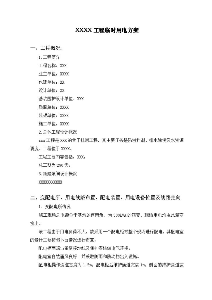
Content introduction 2. Overview of overall project design The xxx project is the backbone of XXX's waterlogging drainage project, whose main tasks are flood control and tide blocking, drainage and waterlogging removal, and water resource scheduling. The project is located in XXXX. The main contents of the project include: XXX. The total construction period is 290 days. 3. Overview of new pump gate design XXXXXXXXXXXX II. Substation and distribution substation, power line layout, power distribution device, location of electrical equipment and line trend 1. Substation and distribution substation conditions The general power supply of the construction site is located in the southwest corner of the foundation pit, which is a 500kVA box transformer substation, and the power used on the site is all connected from this box transformer substation. Because the power load of the project is not large, a distribution cabinet is used to distribute power to the whole site. The design of the distribution room is mainly arranged according to the following conditions: both ends of the distribution cabinet are electrically connected with the repeated grounding wire and the protective zero line. The distribution room has good natural ventilation and is equipped with rain proof and animal proof facilities. The width of the operation channel of the distribution cabinet is 1.5m, the width of the maintenance channel behind the distribution cabinet is 1m, the width of the maintenance channel on the side is 1.5m, and the ceiling of the distribution room is 3m from the ground. The door of the power distribution room is opened outwards and equipped with a lock. The distribution room is equipped with fireproof sand box and insulated fire extinguisher. Each circuit shall be numbered and its purpose shall be indicated. During the maintenance of the distribution panel or distribution line, the power cut sign board shall be hung, and the power cut and transmission shall be in the charge of a specially assigned person. 2. Power line layout The project adopts radial distribution line layout. The whole site is distributed by four main lines, and the route is: general distribution box → distribution box → switch box → electrical equipment. A primary general distribution box is set on the west side of the inland river cofferdam at the southwest end of the construction site, leading out 4 routes: Line 1: mainly responsible for power consumption in the processing area. Line 2: mainly responsible for power consumption in the south production area. Line 3: mainly responsible for power consumption in the north production area. Line 4: mainly responsible for power consumption in the living quarters of employees. 3. The line layout requires that the cable shall be buried after entering the site. The cable from 0.2m underground to 2m above the ground must be provided with a protective sleeve. The laying depth of buried cables shall not be less than 0.7m, and 5cm thick sand layer shall be laid on the top and bottom respectively, then hard protective layers such as bricks shall be covered, and warning signs shall be made. The joint of buried cable shall be set in the junction box on the ground. The power supply in the construction area is arranged by overhead cable wiring.

Special scheme for temporary power supply on construction site - Figure 1

Special scheme for temporary power supply on construction site - Figure 2

Special scheme for temporary power supply on construction site - Figure 3

Special scheme for temporary power supply on construction site - Figure 4

Special scheme for temporary power supply on construction site - Figure 5
Special statement: This material belongs to the sharing uploaded by users Downloaded content, only for learning, not for commercial use. If there is any copyright problem, please timely contact Station delete!
Collection
share
WeChat code scanning and sharing
Click to share


