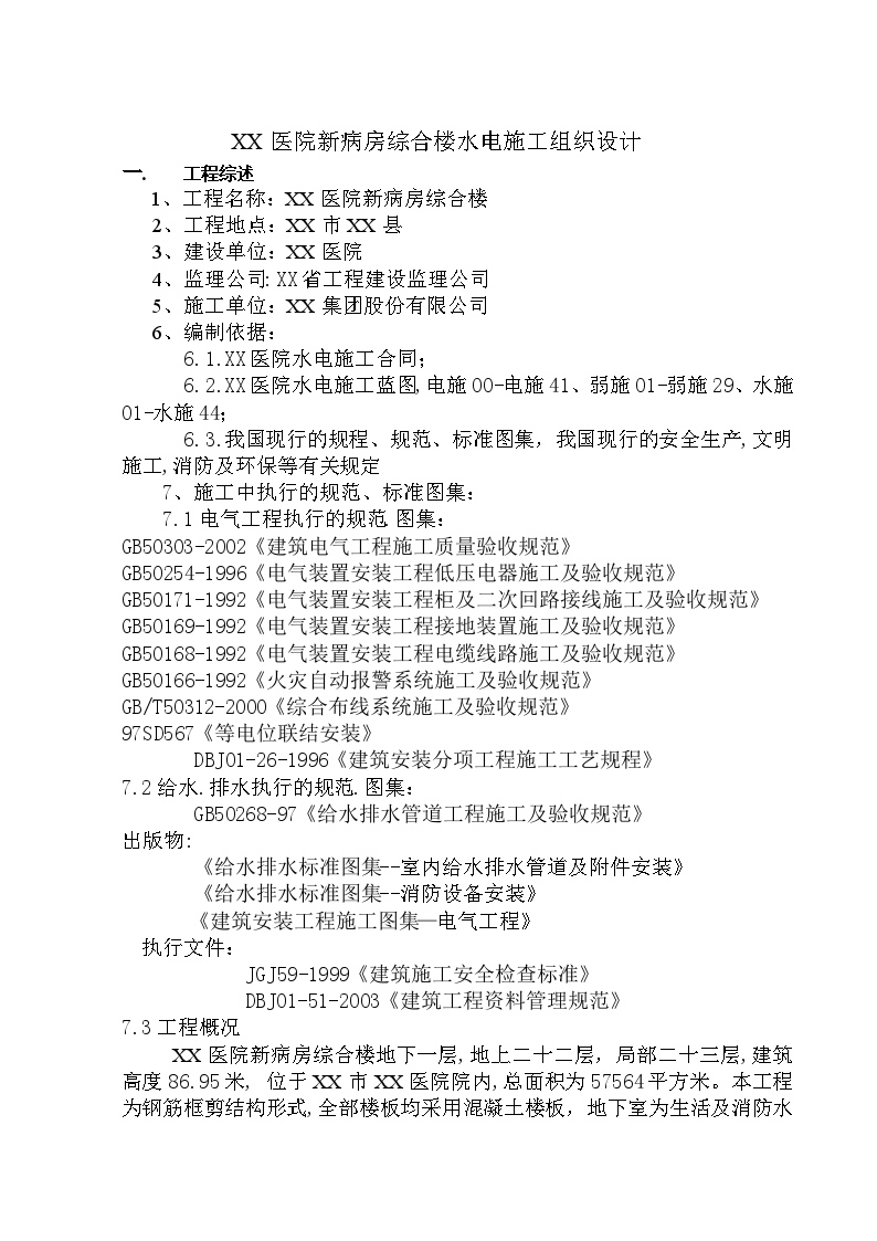
The new ward complex building of XX Hospital has one floor underground, 22 floors above the ground and 23 floors locally, with a building height of 86.95 meters. It is located in XX Hospital of XX City, with a total area of 57564 square meters. The project is in the form of steel bar frame shear wall structure. All floors are concrete floors. The basement is used for living and fire water pump room, power transformation and distribution room, garage, aseptic room, washing and disinfection dressing production room, etc. The first floor is pharmacy, business center, virus test, fire control center integrated wiring room, etc. The second floor is ward, showing education rooms, etc. The third floor is operating room, and the fourth floor is equipment room. The fifth to twenty second floors are wards, of which the ninth floor is an obstetric ward, and the twelfth and thirteenth floors are pediatric wards. The other floors are standard nursing units, and the top floor is the fire pressurization equipment water tank on the elevator machine room floor.

 Construction Organization Design of a Hospital Ward Complex Building - Figure 1

Construction Organization Design of a Hospital Ward Complex Building - Figure 1

 Construction Organization Design of a Hospital Ward Complex Building - Figure 2

Construction Organization Design of a Hospital Ward Complex Building - Figure 2

 Construction Organization Design of a Hospital Ward Complex Building - Figure 3

Construction Organization Design of a Hospital Ward Complex Building - Figure 3

 Construction Organization Design of a Hospital Ward Complex Building - Figure 4

Construction Organization Design of a Hospital Ward Complex Building - Figure 4

 Construction Organization Design of a Hospital Ward Complex Building - Figure 5

Construction Organization Design of a Hospital Ward Complex Building - Figure 5

Click to download the source file now

Special statement: This material belongs to the sharing uploaded by users Downloaded content, only for learning, not for commercial use. If there is any copyright problem, please timely contact Station delete!

Collection
share

WeChat code scanning and sharing

Click to share

  • The 19th floor ward of a hospital Complex building Electrical construction drawing
    This drawing is the electrical construction drawing of the 19th floor sickroom complex building of a hospital. The drawing contains electrical construction design instructions, foundation grounding plan, basement electrical plan, basement fire plan, first floor power plan, etc. The content of the drawing is complete, clear and precise, and designers are welcome to download and use it.
  • [Shandong] Ward of a hospital Complex building Construction organization scheme of electrical works
    In addition to staircase, electrical room, equipment room, pipe well, underground floor, equipment floor and machine room floor, other parts of the building are made of suspended ceiling. Building fire compartment: The first floor underground of the building is divided into two fire compartments, and each floor of the other floors is an independent fire compartment.
  • A hospital ward on the sixth floor Complex building Water supply and drainage design drawing

    This data is the water supply and drainage design drawing of a six floor hospital ward complex building. The drawings include the design description equipment material list, water supply and drainage system diagram, fire protection system diagram, water supply and drainage plan, water supply and drainage plan on the roof floor, water tank axial side view, water supply and drainage plan on the roof floor of the stairway, general layout of water supply and drainage pipelines, etc., which can be used for reference.


  • Inpatient in a hospital in Sichuan Complex building Construction organization design
    The construction organization design of the project is prepared after quality planning in strict accordance with the bidding scope and the requirements of the bidding documents for the construction organization design. It is composed of civil engineering, installation, decoration and other disciplines under the principle of unified deployment of personnel, machinery, material supply, balanced deployment, construction scheme, quality requirements, schedule, etc. Our company attaches great importance to the preparation of the bidding construction organization design of this project, and calls together technical experts who have been engaged in similar engineering work, and relevant responsible persons to overcome the key points, difficulties and construction technology of special parts of this project, so as to make this scheme prominent, responsive, targeted and operable.
  • hospital Complex building Foundation pit construction organization design
    Project name: Geotechnical Engineering of Shenyang Hospital Eye Building. Construction site: No. 36, Middle Road, Shenyang City, west side of South Street, north side of West Road, southwest corner of Shenyang yard. Construction scale: 41353m2 building area, 2 underground floors, 16 above ground floors, frame structure. Designer: Surveyor: Quality requirements: acceptable. Commencement and completion date: May 20, 2007~June 20, 2007. Project content: basement excavation and transportation, foundation pit support and dewatering works. Surrounding area and traffic conditions: Kunshan West Road to the south; Jiuzhou Hotel on the 5th floor in the east; Two 6-storey residential buildings in the west; The north is adjacent to the original dry clinic building on the fifth floor; There are two ward buildings in the northeast corner. The other side of the site is mainly the hospital, which cannot be used as the transportation channel. The south is adjacent to Kunshan West Road, which is the main transportation channel for earthwork and materials. Other conditions: there is a north-south reinforced concrete civil air defense project within the scope of the excavated foundation pit, and there are communication cables passing through the tunnel; There is an east-west HV and LV cable passing through the site.
  • A hospital in Anhui Province Complex building Construction organization design
    **The regional basic wind pressure is 0.30KN/m2. During the rainy season from May to June, the highest temperature is from mid July to mid August, reaching 32~36 ℃, and the lowest temperature is from January to February, reaching - 4~- 5 ℃, which has no great impact on the construction.
  • hospital Complex building Construction organization design scheme
    Chang'an Hospital is located on the west side of Yuanshanbei Section of Huancheng Road, Changping Town. The planned road leading to Guangzhou Shenzhen Expressway (Dalangkou) is in the south of the land, and farmland is in the north and south. The total planned construction land is 101000 square meters.
  • A hospital Complex building Electrical installation construction organization design
    The project is composed of high and low voltage power distribution system, lighting and power system, lightning protection grounding and equipotential bonding system, generic cabling system, cable television system, closed-circuit television monitoring system and ward calling system.
  • A hospital in Hohhot Complex building Construction organization design
    The construction organization design of a hospital complex building in Hohhot includes the project name: Hohhot * * * Hospital Complex Building Project; Construction unit: * * * Hospital of Hohhot City; Designer: Beijing * * * Architectural Design Consulting Co., Ltd; Project location: southwest of the intersection of * * * * Road and * * * * National Highway, starting from the intersection westward to 224 meters and extending westward to 540 meters For reference and download
  • hospital Complex building Organize the design of construction scheme
    The project belongs to Class I hospital building, in which the fire electrical equipment, emergency lighting, medical surgery, medical emergency, etc. are powered by Class I loads, and the rest are Class II and III loads. Class I loads are powered by dual power supply dedicated circuits, and start switching is carried out at the terminal distribution box.
  • hospital Complex building Hydropower construction organization scheme
    The project is located in Hefei, Anhui Province, bordering Guihua Road in the north, Wenqu Road in the east, Wanshui Road in the south, and Chuangxin Avenue in the west. The first phase building is divided into outpatient medical technology building and inpatient building. The total building area of the first phase is 308777.34 square meters. The outpatient medical technology building is connected with the inpatient building and its basement, and connected through the hospital street on the ground. This sub project is an outpatient medical technology building, with a floor area of about 154576.94 square meters. The first and second floors underground are equipment rooms and parking garages- The out-patient lobby, radiology department, emergency emergency center, central operating department, central supply, testing center, digestive center, functional examination center, cardiovascular center, peritoneal dialysis center, etc. are located in the podium from 5.4 m to 3 floors; The equipment room and the overhead floor on the roof are operating room equipment rooms, etc. The building height of outpatient medical technology building is 23.9 meters.
  • A hospital Complex building Elevator installation construction organization
    This project is the elevator installation construction organization design of a hospital complex building. The project includes: 1. unpacking and counting; 2. elevator shaft handover; 3. scaffold erection; 4. safety precautions; 5. setting out and positioning; 6. installation of elevator landing door; 7. installation of guide rail bracket and guide rail
  • Construction Organization Design of Air Conditioning System in Hospital Comprehensive Ward Building
    Project name: Central air conditioning system project of the new ward building of Nanyang xx Hospital Construction unit: Bidding agency: Project location: Scope of work: The new ward building of Nanyang xx Hospital has a total building area of 76500m2, frame shear structure, two floors underground and twenty-two floors above ground. The scope of work covers the installation, commissioning, training, warranty service, cargo related transportation, insurance and other related services of the central air-conditioning terminal system and its auxiliary equipment. The air conditioning cold source of the building is three centrifuge water-cooled chillers, which are placed in the refrigerator room on the ground floor. The air conditioning heat source is the heat exchange station, and the air conditioning water system is the secondary pump system. Ventilation system: mechanical ventilation and mechanical air supply are used in the refrigerator room and water pump room. Mechanical ventilation and mechanical air supply are adopted for heat exchange station and power transformation and distribution station. Quality requirements: on the basis of the qualified standard specified in the Code for Acceptance of Engineering Construction Quality, the project quality shall strive to reach the provincial quality standard, but shall not affect the evaluation of the "Zhongzhou Cup" of the main project. Construction period requirements: all works under the contract shall be subject to the mobilization notice of Party A, and meet the total construction period requirements of the general contractor from the date of notification of mobilization.
  • A hospital Complex building Ventilation construction design
    Abstract: The hospital is located at No. 277, Yanta District, a city (in the medical area of the First Affiliated Hospital of a university), with a total construction area of 50198.8 square meters; One floor underground and five floors above the ground. This design includes the design of air conditioning, ventilation, smoke control and exhaust in the building, negative pressure suction, and purification air conditioning.
  • New ward of a hospital in Qiqihar Complex building Construction organization design of electrical engineering
    This scheme is the construction organization design of the electrical engineering of the new ward complex building of a hospital in Qiqihar, including the preparation basis, construction site organization and professional technical force allocation, construction deployment, etc. It is very practical for reference. PDF file, 67 pages.
  • [Chaoyang] Hospital outpatient ward Complex building Construction Organization Design of Expansion Project (Page 279)
    This project is an expansion project of the Outpatient Ward Complex Building (Pediatrics) of Chaoyang Second Hospital, located in the fourth section of Chaoyang Street, Shuangta District, Chaoyang City, in the hospital of Chaoyang Second Hospital, with a total land area of 1820.7 square meters and 28697.8 square meters above the ground; The underground area is 2713.3 square meters. The finished surface elevation of the basement floor concrete is -6.6 meters. The deepest part of the foundation pit is about 10.6 meters. The foundation form is raft foundation. There are 1 floor underground and 15 floors above the ground, with a total height of about 112.55m.
  • 19th floor ward of a hospital in Zhejiang Complex building Electrical construction drawing
    This project is a hospital ward complex building in Zhejiang, with 19 floors in total and one underground floor. The total construction area is about 30000 square meters, with wards, operating rooms, etc; The structural form is frame structure with cast-in-place concrete floor. The design scope includes 220/380V power distribution system, lighting power distribution system, lightning protection and grounding system, fire protection system, etc. The design is accurate and the content is detailed, which can be downloaded for reference by netizens.
  • Construction organization design of external decoration of hospital ward building
    1. Project name: Door, window and exterior decoration project of ward building of Rizhao Traditional Chinese Medicine Hospital 2. Project location: No. 35, Wanghai Road, Rizhao 3. Structure type: frame structure 4. The ground floor area is 29630.36 m2, 15 floors above the ground, and the building height is about 56.68 m 5. Reasonable service life of 50 years, seismic fortification of 7 degrees 6. Construction content: full concealed frame glass curtain wall, plastic steel doors and windows, frameless doors, etc
  • Construction organization design of a hospital ward building in Shandong
    1. Construction period target Commencement date: March 16, 2005 Completion date: May 20, 2008 2. Project quality requirements: ensure "Taishan Cup, strive for" Luban Prize ". 3. Objective of safe and civilized construction: the construction site of the project shall be managed in accordance with civilized construction site to ensure that it meets the standard of "provincial safe and civilized construction site".
  • Construction organization design of a hospital high-rise ward building
    The construction organization design of a high-rise ward building of a hospital includes the project name: Red Cross Ward Building of ******** * City * * Hospital. Construction unit: * * Hospital of ****** City. Construction site: No. *********, ******* City, Hebei Province. The project is a frame shear wall structure of * * * Hospital in ****** City, with ten floors above the ground and one floor underground. The building is 80.2m long, 32.09m wide and 44.8m high. It covers an area of 2420.68m2, with a building area of 30570.82m2, including 1250m2 of basement. For reference and download
  • Construction organization design of a hospital ward building in Wuhan
    The construction organization design of a hospital ward building in Wuhan includes the project name: surgical ward building of * * * * * * * * * * * * * * * * * * * * * * * * * * * * * * * * * * * * * * * * * * * * * The construction unit in the hospital * * * * * * * * * * * * * * * * * * * * * * * * * * * * * * * * * * * * * * * * * * * * * * * * * * * * * The main subcontractor of CSCEC * * * has no construction period of 690 days. The contract duration is 690 days. The total investment is 219.28 million yuan. The contract duration is 219.28 million yuan. The main function or purpose of the project is surgical ward building
  • A hospital in Nanchang Complex building Project construction organization design
    The project is the civil engineering of the scientific research and medical auxiliary complex building of the First Affiliated Hospital of * * * University, located in the First Affiliated Hospital of * * * University. The total height of the main building is 95.70m, and the project has two underground floors, 4.8 and 4.2m high; There are 23 floors above the ground. The first, third and fourth floors are 4.80m high. The second and twenty second floors are 4.20m high, and the rest are 3.60m high.
  • A hospital in Liaoning Province Complex building Curtain wall construction organization design
    . 6 Construction machine and tool plan: 1.6.1. Main machines and tools, equipment arrangement and use plan Machines and tools, equipment supply plan is an important part of machine and tool management, reasonable machines and tools, equipment supply plan is to ensure the smooth progress of construction production. The corresponding equipment specifications and quantities are strictly in line with the use requirements of the construction site, which is the key point. In order to ensure that the project can be completed in a high-quality, efficient and smooth manner according to the plan requirements of the construction period, our company takes the following measures for the allocation of machines, tools and equipment: A. Prepare a reasonable supply plan for machines, tools and equipment Performance and other aspects must be able to meet the needs of project construction. Reasonably arrange the reasonable allocation of various machines, tools and equipment in time and space between construction teams and at each construction stage to improve the use and working efficiency of machines, tools and equipment. B. According to the requirements of the construction schedule, prepare machines, tools and equipment, prepare transport and mobilization plans for machines, tools and equipment, and ensure timely and safe mobilization. C. Strengthen the repair and maintenance of machines, tools and equipment on site, improve the intactness and utilization rate of machines, tools and equipment, and make the quantity and quality of machines, tools and equipment planned to supply meet the construction requirements. D. Reasonably organize the construction to ensure the continuity of the use of construction and production machines and equipment.
  • High level of a hospital in Urumqi Complex building Construction organization design
    The construction organization design of a high-rise complex building of a hospital in Urumqi includes the construction site: this project is the comprehensive business building project of * * Hospital in Urumqi. The construction site is located at * * East Road, * * District, Urumqi. 2. Structure type: the structure of this project is frame shear wall structure; The building structure is classified as Class B. 3. Construction area: the total construction area of Phase I is 50816.99 ㎡, including 48589.79 ㎡ above the ground and 2227.20 ㎡ underground. 4. The number of floors and height of the building: 23 floors above the ground, 1 floor underground, the total height of the building is 97.30m. 2、 Requirements for main building materials can be downloaded for reference
  • A frame shear hospital in Tianjin Complex building Construction organization design
    Optimize the configuration of construction machines and tools: use advanced construction machines and tools as far as possible, and equip enough conventional small construction machines and tools to improve labor productivity. Special personnel shall be assigned to take charge of the storage, maintenance and repair of construction machines and tools, instruments and meters, so as to ensure the intactness of construction machines and tools and the accuracy of instruments and meters, and avoid affecting the project progress due to construction machines and tools.
  • A hospital in Sichuan Complex building Construction organization design (post disaster reconstruction)
    1. The annual estimated number of lightning strikes of the project is N=0.0554 (times/a), which belongs to the third category of lightning protection buildings. The lightning protection device of the building shall meet the requirements of preventing direct lightning, lightning induction and lightning wave invasion, and shall be equipped with general equipotential bonding. 2. Lightning arrester: φ 10 hot-dip galvanized round steel is used as lightning strip on the roof, which is exposed along the parapet. 3. Downlead: two main reinforcements above φ 16 in the reinforced concrete column of the building shall be welded in full length as the downlead, and the distance between the downleads shall not be greater than 25m. A 40X4 hot-dip galvanized flat steel is led out from the downlead of all external walls 1m below the outdoor ground. The flat steel extends out of the room, and the distance from the outer wall is not less than 1m. 4. Grounding electrode: the grounding electrode is the foundation grounding grid formed by the welding and binding of two main reinforcements in the upper and lower layers of reinforcement on the foundation bottom beam of the building. 5. The upper end of the downlead is welded with the lightning strip, and the lower end is welded with the grounding electrode. Test points shall be set at 0.5m above the outdoor ground for the external wall downlead at four corners of the building. 6. All metal components, metal ventilation pipes, metal roofs, metal roof trusses, etc. protruding from the roof shall be reliably welded with the lightning strip. 7. All welding points of outdoor grounding shall be painted with asphalt for corrosion prevention. Grounding and safety measures: 1. The lightning protection grounding, protective grounding of electrical equipment, etc. of the project share a unified grounding electrode, and the grounding resistance is required to be no more than 1 ohm. If the actual measurement does not meet the requirements, an artificial grounding electrode shall be added. 2. All metal shells of electrical equipment that are normally uncharged and may present voltage when the insulation is damaged shall be reliably grounded. 3. The project adopts general equipotential bonding. The general equipotential board is made of copper plate. The protection trunk line and equipment incoming main pipe in the building shall be connected. The general equipotential bonding line adopts BV-1X25mm2PC32. The general equipotential bonding adopts equipotential clips. Welding on metal pipes is prohibited. The equipotential box is concealed, and the bottom edge is 0.3m from the ground. See the national standard atlas Installation of Equipotential Bonding 02D501-2 for details. 4. Over voltage protection devices shall be set at cable TV system lead-in end, telephone lead-in end, etc. 5. The project is TN-S system from the main cabinet and distribution box. The power supply is repeatedly grounded at the incoming line, and PE line is set separately, and the grounding electrode is shared with the roof. The weak current department of the project only conducts pipeline design for weak current. The contractor is responsible for the detailed design of weak current system, and the design institute is responsible for the review and coordination of interfaces of other systems. Weak current signals are introduced from the outdoor underground. Emergency lighting: the walkway is equipped with emergency lighting, and batteries are used as standby power supply. The emergency time shall not be less than 30min. The emergency lighting circuits in the plan are all three lines. The emergency lighting is charged at ordinary times, and will be automatically lit when power is cut off. 2、 Overview of water supply and drainage project: design scope of the project: indoor and outdoor water supply, sewage, rainwater design; Indoor and outdoor fire protection system. Water fire extinguishing system control device.
  • Outpatient of a hospital in Binzhou Complex building Construction organization design
    This document is the construction organization design of the outpatient complex building of a hospital in Binzhou. This project is the outpatient office complex building project of the * * affiliated hospital * * in Binzhou. It is a full cast-in-place frame structure system. The podium building has three floors and the main building has ten floors, with a total floor area of 20873 square meters; The first floor is 4.5 meters high, the second and third floors are 4.2 meters high, the fourth floor is 3.9 meters high, the sixth to tenth floors are 3.9 meters high, the machine room floor is 3.6 meters high, the total height of the building is 39.95 meters, and the indoor and outdoor height difference is 0.45 meters; The content is detailed and can be downloaded for reference by netizens.
  • Construction Organization Design of Decoration Project of High rise Comprehensive Ward Building in Hospital
    The decoration project of the high-rise comprehensive ward building of XX Central Hospital is located in the central hospital of Gongnong Road, XX City, Henan Province. The structure of the project is frame shear wall structure. The main body of the project is 22 floors, the building height is 94.6m, and the construction area of the project is 76500.7 ㎡. The ward building is a landmark building in XX City, which is one of the few modern ward buildings in Henan Province. The podium mainly consists of two operating departments and supporting rooms, and the main building is the ward of each department. Our company undertakes the interior decoration of podium building 1-4 and wards on floors 3-22 in this section.
  • [Henan] Construction Organization Design of Air Conditioning System in Hospital Comprehensive Ward Building
    This manuscript is the construction organization design of the terminal installation project of the central air conditioning system in a new ward building of a hospital in Nanyang City, Henan Province; The building has a total floor area of 76500m2, a frame shear wall structure, two floors underground and twenty-two floors above the ground. The scope of work covers the installation, commissioning, training, warranty period services, cargo related transportation, insurance and other related services of the central air-conditioning terminal system and its auxiliary equipment; The air conditioning cold source of the building is three centrifuge water-cooled chillers, which are placed in the refrigerator room on the ground floor. The air conditioning heat source is a heat exchange station, and the air conditioning water system is a secondary pump system. Ventilation system: mechanical ventilation and mechanical air supply are used in the refrigerator room and water pump room. Mechanical ventilation and mechanical air supply are adopted for heat exchange station and power transformation and distribution station. Installation of supports and hangers for air ducts: ◆ Supports and hangers with different diameters are used for air ducts of different sizes according to the requirements of the specification. The length of the suspender shall be taken and processed according to the size and installation height of the air duct and the height of the floor. The end of the suspender shall meet the requirements of adjusting the elevation of the air duct. After the suspender is made, it can be installed according to the layout direction of the air duct, and the spacing shall meet the requirements of the design and specifications. ◆ The hanger of the suspender shall be processed with angle steel, and the qualified supports and hangers shall be rust proofed in time. ◆ Before the installation of supports and hangers, the surveying and setting out shall be carried out first, and then the supports and hangers shall be reliably fixed on the concrete structure, or fixed on the steel structure by drilling and welding. ◆ The installation and stressed parts of the support must comply with the provisions of the design or relevant standards. The support shall be firmly and tightly fixed on the wall, column or other structures. The support shall be installed horizontally. The suspender of the hanger shall be perpendicular to the pipe. The supports and hangers shall be arranged in order. ◆ Air duct supports and hangers: Fire damper, electric fire control valve and other components must be installed with separate supports and hangers. Generally, the air duct is provided with one support and hanger every 3 meters. The practice of support and hanger can refer to the national standard atlas of heating and ventilation. The insulation air duct must be padded with hardwood mat brushed with fireproof paint between the air duct wall and the cross arm of supports and hangers. ◆ The supports and hangers shall not be set at the air outlet, valve, inspection door and automatic control mechanism. The suspender shall not be directly fixed on the flange. ◆ Set an anti shaking support with angle iron every other two hangers.
  • Construction Design of the General Ward Building of the People's Hospital
    1. General situation of concrete works All commercial concrete is used in this project. The underground concrete is poured with a combination of truck pump and fixed pump, and the ground pump is used for transportation. 2. Preparation before concrete pouring (1) Preparation of machines and tools and inspection Before concrete pouring, prepare and implement the hopper, vibrator, vibrating rod, concrete pump and other machines and equipment as required. Vulnerable machines and tools shall be kept in reserve. All machines and tools used shall be checked and commissioned before pouring, and full-time technicians shall be available for maintenance at any time. (2) Ensure the water and electricity supply during the concrete pouring, and ensure that the on-site water, electricity and lighting are not interrupted. Contact the water and electricity supply department in advance. To prevent power failure, standby generator. (3) Grasp the weather conditions and strengthen the contact with the meteorological department for prediction and forecast. When pouring concrete in each construction section, grasp the weather changes and try to avoid rainy days to ensure the quality of concrete pouring. (4) Check the size, specification, quantity and position of formwork, support, reinforcement and embedded parts. Before concrete pouring, check and control the size, specification, quantity and position of formwork, reinforcement, steel skeleton, protective layer and embedded parts. The deviation shall meet the requirements of construction specifications. Pay attention to the following points during inspection: 1) Whether the elevation and position of formwork and the section size of components meet the design requirements. 2) Whether the installed support is stable; Whether the support and formwork are fixed reliably. 3) Before concrete pouring, the garbage and wood chips in the formwork shall be removed. (5) Make technical preparation and make technical disclosure to construction personnel. The Employer and the Supervisor shall accept the concealed parts and fill in the concealed acceptance records. Strictly implement the concrete pouring order system. Fill in the concrete mixing notice and inform the concrete mixing plant of the mix proportion, mixing amount and pouring time of the concrete to be poured. 3. Transportation and pumping of concrete (1) Due to the large single floor area of the building, commercial concrete is transported to the pump truck parking point on the site with a mixer truck. The transportation time shall not exceed 2 hours. During transportation, it is strictly prohibited to add water. After each truck of concrete is transported to the site, it is required to take samples at random to measure the slump, and can be used only after it is qualified. The rotation speed of the mixer shall be in accordance with the different requirements of the mixing station for loading, mixing, unloading, etc. or the requirements of the mixer product manual to ensure product quality. (2) Concrete pump pipe laying 1) The straight pipe of the concrete transmission pipeline shall be arranged smoothly, the pipe joints shall be dense without mortar leakage, and the anchoring at the turning position shall be firm and reliable. 2) The distance between the concrete pump and the vertical upward pipe should be greater than 15m to counteract the impact of falling back and ensure that the vibration of the pump does not directly transmit to the vertical pipe. 3) The position where the pipeline passes through shall be flat, and the pipeline shall be fixed with supports or wood bracing, and shall not directly contact with the formwork and reinforcement. If it is placed on the scaffold, reinforcement measures shall be taken. 4) When the vertical pipe passes through the floor, it shall be anchored with timber or embedded bolts. 5) For the delivery pipe newly connected during construction, the sundries in the pipe shall be removed first, and the pipe wall shall be lubricated with water or cement mortar. (3) Concrete pumping The concrete pumping of this project mainly uses ground pump and automobile pump. Before concrete pumping, wet the hopper, pump room and pipeline of the pump truck with proper amount of water. After checking that the pipeline is normal, lubricate and press it with 1:1 cement mortar. At the beginning of pumping, the pump should be in a low speed running state, with a speed of 500~550r/min. Pay attention to the pressure of the pump and the working condition of each part. The delivery pressure is generally not more than 1/3 of the maximum working pressure of the main cylinder of the pump. The normal operating speed can be increased only after the pump can be pressed smoothly. The pumping of concrete shall be continuous. When the concrete supply is insufficient or the operation is abnormal, the pumping speed can be slowed down to maintain continuous pumping. The slow pumping time shall not exceed the allowable duration from mixing to completion of pouring. When it is difficult to press concrete, the pressure of the pump rises, and the pipeline vibrates, do not press the concrete by force. Check the pipeline first, and slow down the pressure or make the pump reverse to prevent blockage. When the delivery pipe is blocked, the mallet can be used to knock the pipe to find the blocked pipe section. After the concrete is depressurized, the blocked pipe section shall be removed, the blockage shall be taken out, and the rest of the pipes shall be checked for blockage. If there is no blockage, the pipe shall be connected again. When re pressing, first exhaust the air, and then tighten the removed pipe joint clamp. During pumping, it shall be noted that the concrete in the hopper shall not be 200mm lower than the upper opening of the hopper. In case of air suction, immediately make the pump run in the opposite direction. After the concrete is sucked into the hopper and the air is discharged, the concrete can be pressed. In the process of pumping concrete, if the interruption time of pumping exceeds 30min or it is difficult to press, the concrete pump shall be pushed at intervals, and four strokes shall be reversed every 4-5min to prevent concrete segregation or blockage.
  • Outpatient ward of a hospital Complex building Fire fighting construction team
    Content introduction The project is the purchase and installation of fire-fighting system equipment for the outpatient ward complex building of the hospital - fire water tank, automatic fire alarm system, automatic sprinkler system, fire telephone, hydrant system, water spray system, gas fire extinguishing system and fire linkage system.
  • Ward of a hospital Complex building Bidding Document for Fire Protection Engineering
    The project is located in a town, with a building height of 36.55m and one floor underground; Main contents include: fire alarm system, water fire extinguishing system, fire ventilation system, etc
  • hospital Complex building Water and electricity construction organization scheme
    Installation scope: water supply and drainage, electrical (including lighting, power electricity, lightning protection and grounding), all contents indicated in the construction drawings (but excluding power transformation and distribution equipment and outdoor installation works). This document is the water and electricity construction organization design scheme of the hospital complex building project, 86 pages in total.
  • Ward of a hospital Complex building Construction scheme of electrical works
    S/N Item 1 Project name New Ward Complex Building of XX Hospital 2 Project overview The project is the new ward complex building of XX Hospital, with one floor underground, twenty-two floors above the ground and twenty-three floors (machine room) locally. The total building height is 86.95 meters, and the total building area is 57564 square meters. It is a Class I high-rise building. The underground floor of the building is used for living and fire pump room, power transformation and distribution room, warehouse, aseptic warehouse, washing and disinfection, dressing production, etc. The first floor is the pharmacy, business center, ward test, fire control center, generic cabling room, etc. The second floor is the ward, showing classrooms and other rooms. The third floor is the operating department. The fourth layer is the equipment layer. The fifth to twenty second floors are wards, of which the ninth floor is an obstetric ward, the twelfth and thirteenth floors are pediatric wards, and the other floors are standard nursing units. The top floor is the elevator machine room, fire booster equipment water tank room, etc. The project adopts frame shear wall structure, and all floors are cast-in-place concrete floors. In addition to staircase, electrical room, equipment room, pipe well, underground floor, equipment floor and machine room floor, other parts of the building are made of suspended ceiling. Building fire compartment: The first floor underground of the building is divided into two fire compartments, and each floor of the other floors is an independent fire compartment. 3 Project location: 4 Square Street, XX County, XX City Construction unit: XX Hospital 5 Supervision company: XX Provincial Engineering Construction Supervision company
  • 3889.14 ping hospital ward on the 6th floor Complex building Water supply and drainage construction drawing
    This data is the water supply and drainage construction drawing of a 6-floor 3889.14 square hospital ward complex building. The building is 49.4 meters long and 24.2 meters wide. The content includes: water supply and drainage plan of the second floor, drainage system plan, water supply and drainage plan of the first floor, etc. The content is detailed and can be used for reference.
  • Ward of a hospital in Hangzhou Complex building Construction scheme for earthwork excavation
    **The Ward Complex Building Project of the First Affiliated Hospital of the Medical College was constructed by the Second Construction Company of * * Construction Group Co., Ltd. This project is located in the First Hospital of * *. Water and electricity have been connected to the construction site, and the entrance and exit are on the Nanchao * * Road. 2、 Earthwork excavation and safety requirements Earthwork excavation requirements:. (2) The surcharge within 6m around the foundation pit shall not exceed 15kp
  • 6th floor of hospital Complex building (Outpatient ward) electrical design and construction drawing
    Building area: 14873m. Floor area: m. Building floors: 6 floors above ground and 1 floor below ground. Building height: m. Structure type: frame. Seismic fortification intensity: degree. The drawings include: description, material list, system diagram, plan, detail drawing, etc.
  • 3889.14 ping hospital ward on the 6th floor Complex building Cad construction drawing of water supply and drainage design
    This drawing is the water construction drawing of 3889.14 Ping Hospital Ward Complex Building with a length of 49.4 meters and a width of 24.2 meters. The contents include water supply and drainage plan of each floor and roof, water supply and drainage fire protection system diagram, water tank axial side view, and general layout of water supply and drainage pipeline. The contents are detailed for reference.
  • 6-floor L-type county hospital ward Complex building Construction drawing of water supply and drainage design
    This drawing is the water supply and drainage design and construction drawing of the 6-floor L-type county hospital ward complex building, including the water supply and drainage plan of each floor, the fire water supply and drainage system, the water supply and drainage plan and system diagram of the toilet, and other drawings. The contents are detailed and can be used for reference.
Click to see more
All comments I want to comment
No comment