Uploaded on: 2020-03-03 10:11:15
zero
5 points

B Ramp Bridge: the bridge center stake number BK0 + 697.5 has a span of 3 × (4 × 20)+4 × 25+2 × (27+30+27)+2 × (3 × 19.5)+2 × (3 × 40) m PC simply supported T beam and PC continuous cast-in-place box beam. The bridge has a total length of 868.5m and a deck width of 10.5m. The bridge overpasses Ramp A bridge and the main line of Shenyang Haikou Expressway. This bridge is located on the circular curve with R=280 and R=2000 and the connected transition curve. The prestressed cast-in-place continuous box girder of the whole bridge has a total of 5 pairs of 16 holes, all of which are double box and double chamber prestressed continuous box girders. The longitudinal and transverse slopes of the bridge deck are jointly adjusted by the thickness of the capping beam, abutment cap transverse slope and bridge deck pavement, and the transverse gradient is 0.07% - 6%. The cast-in-place pier is 12.2m to 17.3m high. C ramp bridge: the bridge center chainage is CK0+649.478, the bridge span is (4 × 25+5 × 25+5 × 20+4 × 20) m PC continuous T-beam+(30.8+40+18.2+21) m PC continuous cast-in-place box beam+(4 × 20+4 × 25+3 × 25) m PC continuous T-beam, the bridge width is 13 m, the total length of the bridge is 773.5 m, and it spans the main line of Shenyang Haikou Expressway. This bridge is located on the circular curve and transition curve section. Most piers and abutments are set along the normal direction of the design line, and 21 # and 22 # piers are arranged obliquely. The Wulian 110m Shenyang Haikou Expressway is a prestressed continuous box girder with the same bridge width, 13m wide, and the most unfavorable clearance under the second span bridge is 5.63m.

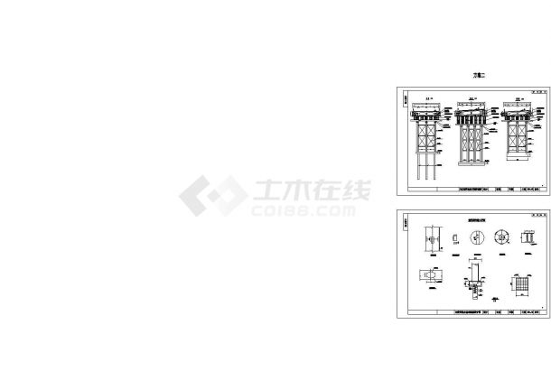
 CAD construction drawing for cast-in-place box girder support design of super large interchange (11 sheets) - Figure 1

CAD construction drawing for cast-in-place box girder support design of super large interchange (11 sheets) - Figure 1

 CAD construction drawing for cast-in-place box girder support design of super large interchange (11 sheets) - Figure 2

CAD construction drawing for cast-in-place box girder support design of super large interchange (11 sheets) - Figure 2

 CAD construction drawing for cast-in-place box girder support design of super large interchange (11 sheets) - Figure 3

CAD construction drawing for cast-in-place box girder support design of super large interchange (11 sheets) - Figure 3

 CAD construction drawing for cast-in-place box girder support design of super large interchange (11 sheets) - Figure 4

CAD construction drawing for cast-in-place box girder support design of super large interchange (11 sheets) - Figure 4

 CAD construction drawing for cast-in-place box girder support design of extra large interchange (11 sheets) - Figure 5

CAD construction drawing for cast-in-place box girder support design of extra large interchange (11 sheets) - Figure 5

Click to download the source file now

Special statement: This material belongs to the sharing uploaded by users Downloaded content, only for learning, not for commercial use. If there is any copyright problem, please timely contact Station delete!

Collection
share

WeChat code scanning and sharing

Click to share

Click to see more
All comments I want to comment
No comment