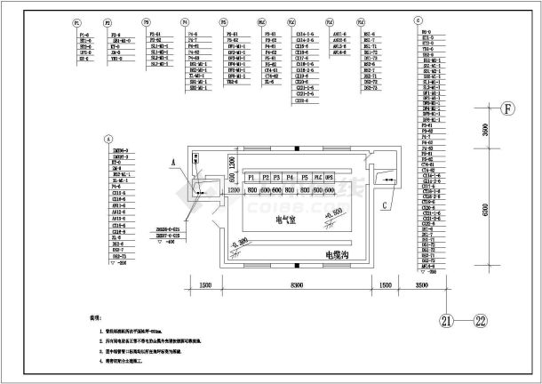
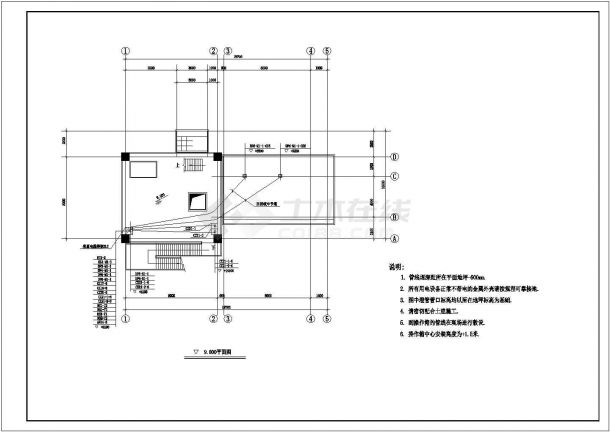
Construction scheme for ash pump room and ash silo gasification fan room of ash handling system in a power plant in Hubei
This project is the ash pump room and ash silo gasification fan room of Hubei * * * Power Plant Phase I Project. The structural part of the project: the design service life of the structure is 50 years, the safety level of the building structure is Level II, the soil category of the building site is Level I, the seismic level of the frame is Level IV, the seismic fortification intensity is 6 degrees, and the design elevation of ± 0.000 meters is equivalent to the absolute elevation of 60.800 meters. The diagonal coordinate position is A=2242.40m, B=1409.70m;A=2255.40m,B=1379.70m。 The structure is horizontally divided into six axes, namely, 1, 2, 3, 4, 5 and 6, with a spacing of 6000 mm, and vertically divided into three axes, A, B and C, with a span of 6500 mm. The pool body is divided into indoor and outdoor parts by the partition wall of Axis A. The outdoor part is 20.625 meters long and 4.1 meters wide, the base elevation is -4.030 meters, the bottom plate thickness is 500 mm, the indoor part is 19.600 meters long and 10.000 meters wide, the base elevation is -4.530 meters, the bottom plate thickness is 500 mm, the pool bottom plate is added with a 100 mm thick concrete cushion, each side is 100 mm wider than the pool side, and the side wall thickness is 400 mm. The indoor pool body is provided with a 1500 mm wide overhanging plate on the north and south sides, The elevation of slab top is ± 0.030m. There are four 1600 × 4506 × 630mm foundations in the pool, and a steel ladder is set at the northeast corner of the pool. There is a cable trench sharing the wall with the pool body between 1-2 lines. The above ground part of the project is a two-layer reinforced concrete frame structure, with a building height of 8.300m, and the elevations of each floor are 3.300m and 8.300m respectively. The 3.300m floor is a ring of tie beams along the outer frame columns, with a section size of 250 × 600mm. The section size of the frame columns is divided into 400 × 600mm and 400 × 400mm; A 5t electric single beam bridge crane is set at 6.000m elevation of A-C axis 1-6 line; The section size of the roof beam on the 800m floor is divided into three types: 250 × 550mm, 250 × 600mm and 400 × 1300mm. The thickness of the roof slab is 100mm. Materials of the project: the strength grade of concrete for foundation, ground beam, frame column, beam, slab and equipment foundation is C30; The cushion is C10; The pool is made of C30 self waterproof concrete with impermeability grade of W6. Thickness of concrete cover: 40mm for foundation, 35mm for beam and column, and 15mm for slab. HPB235 (Grade I) and HRB335 (Grade II) reinforcement shall be adopted; The steel is Q235B. E43 welding rod is used for HPB235 steel, and E50 welding rod is used for HRB335 steel. Anchorage and overlapping length of load-bearing reinforcement: the anchorage length of HPB235 reinforcement is not less than 24d, and the overlapping length is not less than 34d; The anchorage length of HRB335 reinforcement shall not be less than 30d, and the lap length shall not be less than 42d. All beam column joints of the frame shall be constructed according to the requirements of 03G101-1 atlas. Building: The building area of the project is 415 square meters, the fire resistance rating is Grade II, and the roof waterproof rating is Grade II. The parapet of frame structure wall is made of MU5 shale brick, and A3.5 aerated concrete block is used above 0.0m, with wall thickness of 250mm. M5 cement mortar is used below parapet and damp proof course, and M7.5 mixed mortar is used above other damp proof course. The damp proof course is 20 thick 1:2 cement mortar (mixed with waterproof agent of 5% cement), which is set at -0.06m. The exterior wall is mainly painted with gray white acrylic exterior wall paint, and the decorative color is blue acrylic exterior wall paint. The scope of this construction covers the excavation, backfilling, foundation, beam, column, slab, masonry, decoration, painting, waterproof and drainage construction of the ash pump room and ash silo gasification fan room.


