Modern communication technology
- SDN and NFV technical characteristics
-
The biggest feature of SDN is that it realizes the separation of control and forwarding. The network equipment is separated into separate control equipment and forwarding equipment. The forwarding equipment functions are simplified. The standard Openflow protocol is followed between control and forwarding, which makes the equipment and network performance more efficient and further subdivides the industrial chain; Centralized control of network resources, computing resources, storage
-
2015-4-27 15:36
- Matched filter receiver
-
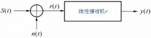
In additive white Gaussian noise (AWGN) channels, matched filters can be used to achieve optimal reception of digital signals. The matched filter is an optimal linear filter. It is a linear filter designed under the criterion of maximum output signal-to-noise ratio
-
2015-3-25 09:45
- Best reception criteria
-
1. The maximum output signal-to-noise ratio criterion is at the moment. If the output terminal of the linear receiver obtains the maximum signal-to-noise ratio, it is considered as received. 2. The minimum mean square error criterion requires the minimum mean square error between the actual output waveform and the expected waveform of the linear receiver. 3. Maximum Likelihood Criterion (ML Criterion) Graph
-
2015-3-25 09:44
- Main factors affecting reliable signal transmission
-
There are two main factors affecting the reliable transmission of signals: 1) The channel characteristics are not ideal; 2) The presence of noise in the channel. Therefore, improving channel characteristics and reducing channel noise is one of the methods to improve the reliability of communication systems; But on the other hand, it can also improve the reliability of the communication system, that is, using the best
-
2015-3-25 09:43
- M-ary digital modulation system
-
1、 The time expression of M-level modulation signal with M-ary amplitude modulation principle and anti noise performance is as follows: the waveform of 4ASK signal shown in Figure 1, the waveform of 4ASK signal shown in Figure (b) of 4ASK signal can be equivalent to the sum of four waveforms in Figure (c), of which three waveforms are divided
-
2015-3-25 09:43
- Comparison of various binary digital modulation systems
-
1、 When the symbol rate is the same, the bandwidth occupied by 2ASK, 2PSK and 2DPSK is narrower than that of 2FSK, and the bandwidth of 2FSK is. Therefore, if the channel bandwidth is tight, the 2FSK mode should not be considered. Band utilization is an effective indicator of digital transmission systems
-
2015-3-25 09:40
- Binary Absolute Phase Shift Keying (2PSK) and Relative Phase Shift Keying (2DPSK)
-
Concept: Binary phase shift keying (2PSK and 2DPSK) uses binary digital baseband signal to control the phase of continuous carrier, and its phase carries the information of digital baseband signal. Binary phase shift keying can be divided into binary absolute phase shift keying (2PSK) and binary relative phase shift keying (2DPSK). ...
-
2015-3-25 09:39
- Binary amplitude keying (2ASK)
-
Amplitude shift keying (also known as amplitude shift keying) is recorded as ASK (Amplitude shift keying), also known as on-off keying (or switch keying), and recorded as OOK (On Off keying). Binary amplitude keying is usually referred to as 2ASK. 1、 2ASK signal time-domain and frequency-domain analysis 1. Basic principle binary
-
2015-3-25 09:35
- Block diagram of digital modulation system principle
-
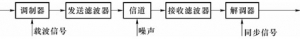
In modern communication systems such as satellite communication, mobile communication, digital microwave communication, optical fiber communication, etc., digital modulated signals are transmitted in channels, which are called digital modulation systems. The digital modulation system composed of modulator, demodulator and modulation channel is shown in Figure 1. Figure 1 Principle block of digital modulation system
-
2015-3-25 09:31
- Time domain equalization
-
In baseband transmission, inter symbol interference (ISI) is the main factor affecting the transmission quality in addition to noise. The inter symbol interference can be eliminated by carefully designed transmission filter and reception filter. However, in actual communication, the overall transmission characteristics will deviate from the ideal characteristics, which will result in inter symbol interference. To overcome
-
2015-3-25 09:31
- Eye diagram
-
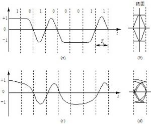
Eye diagram: a method of estimating system performance by means of experiments. It refers to observing the received signal waveform with an oscilloscope to judge the transmission quality of the system. Specific method: Connect the oscilloscope across the output end of the receiving filter, and then adjust the horizontal scanning period of the oscilloscope. When the horizontal scanning period of the oscilloscope is adjusted
-
2015-3-25 09:29
- Anti noise performance of digital baseband transmission system
-
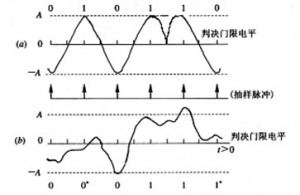
The influence of channel noise on baseband transmission system without inter symbol interference is discussed below, assuming that the channel noise is additive white Gaussian noise with mean value of 0. 1、 Digital baseband signal reception If the baseband transmission system has neither inter symbol interference nor channel noise, the sampling decision can be error free
-
2015-3-25 09:29
- Digital baseband system without intersymbol interference
-
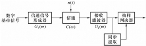
1、 The model of digital baseband transmission system The baseband transmission system is mainly composed of four parts: transmission filter, channel, reception filter and sampling decider. In order to ensure the reliable and orderly operation of the system, there should also be a synchronous system. Figure 1 Block diagram of digital baseband transmission system
-
2015-3-25 09:26
- Power spectral density of digital baseband signal
-
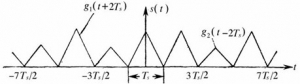
1. Digital baseband signal waveform (binary) Figure 1 Schematic waveform of arbitrary random binary pulse sequence Set a sample function of random binary sequence as shown in Figure 1. Order "0" representing binary symbol, "1" representing binary symbol, symbol interval is, digital baseband signal can be represented as
-
2015-3-25 09:25
- Digital baseband signal
-
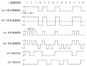
Digital baseband signal: the radio wave shape of the message code. 1、 Binary code refers to the code type with only two levels of binary code amplitude. Figure 1 shows the waveforms of several commonly used binary codes. Figure 1 Several commonly used binary code waveforms 1 Unipolar non return to zero code is used in this kind of binary code
-
2015-3-25 09:24
- Digital Baseband Transmission Systems
-
Baseband signal: the original data signal from the data terminal, such as the binary sequence output by the computer, the code output by the telex, or the PCM code group from the analog signal after digital processing, are digital signals. These signals often contain rich low-frequency components, even DC components, called digital base
-
2015-3-25 09:22
- Frequency division multiplexing and application examples
-
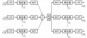
1、 Frequency division multiplexing concept: multiplexing is to combine several unrelated message signals together and transmit them in one channel. Advantages: improve channel utilization. Multiplexing methods: frequency division multiplexing and time division multiplexing. Frequency division multiplexing (FDM): It is used to distinguish signals by frequency
-
2015-3-25 09:22
- Comparison of various analog modulation systems
-
Comparison conditions: 1) There is no DC for baseband signal, i.e; 2) The input power of the demodulator is the same; 3) The noise considered by each system is the same, which is white noise with zero mean, Gaussian and unilateral power spectral density; 4) The bandwidth of the modulated signal is the same. When the modulated signal is a single frequency signal, and
-
2015-3-25 09:20