
Author: Tao Jinliang, senior client development engineer of Netease Yunxin
In recent years, the field of real-time audio and video has become more and more popular. Many audio and video engines in the industry are implemented based on WebRTC. This paper mainly introduces the demand background of WebRTC on video auxiliary stream and the implementation of related technologies.
SDP in WebRTC supports two schemes: PlanB scheme and Unified Plan scheme. In the early days, the Plan B scheme using multiple PeerConnections only supports sending one video stream, which we call "mainstream". At present, we use the Unified Plan scheme of single PeerConnection to add a video secondary stream. What is the video "secondary stream"? Video sub stream refers to the second video stream, which is generally used for screen sharing.
Demand background
With the development of the business, one way of video streaming can not meet the needs of more actual business scenarios. For example, in multi person video chat, NetEase conference and other online education scenarios, two ways of video streaming need to be sent at the same time: one way is camera streaming, and the other is screen sharing streaming.
However, currently, when using the SDK to share screens, we use the camera acquisition channel to share screens. In this scheme, the sharer has only one uplink video stream. In this scenario, either the uplink camera image or the uplink screen image is mutually exclusive.
Unless a new SDK specifically collects and sends screen images, the solution of two SDKs in the instance is troublesome and has many problems in the business layer, such as how to handle the relationship between two streams.
In the WebRTC scenario, there is also a scheme that can independently open all the upstream video streams for screen sharing, which is called "Substream" 。 Secondary stream sharing means that the sharer releases the camera image and screen image at the same time.
In addition, with this auxiliary flow channel, when the device is a new version of iPhone (the new version of iPhone has the ability to simultaneously turn on the front and rear cameras), it also lays the foundation for supporting the front and rear 2-way cameras to send video data.
Technical background
The early SDK architecture design is a multi PeerConnection model, that is, one PeerConnection corresponds to one audio and video stream. With the introduction and support of the new SDP (Session Description Protocol) format (UnifyPlan), a PeerConnection can correspond to multiple audio and video streams, that is, a single PeerConnection model, that is, a single PC based architecture, Allow to create multiple transceivers for sending multiple video streams 。
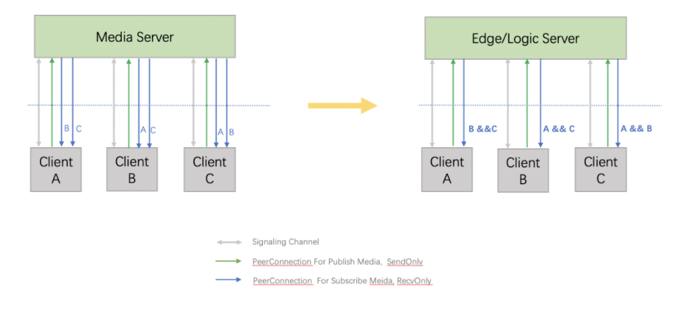
Technical implementation
At present, video streams are mainly divided into three categories: Camera stream, screen sharing stream and custom input video stream, which have different attributes:
- Camera stream is the mainstream and Simulcast is supported;
- Custom video input (non screen sharing) is the mainstream, and Simulcast is not supported;
- Screen sharing is regarded as a secondary stream, which does not support Simulcast and has a separate screen sharing coding strategy;
Due to the particularity of iOS screen sharing, it needs to obtain video data through customized video input, so there is a flow chart as shown below:
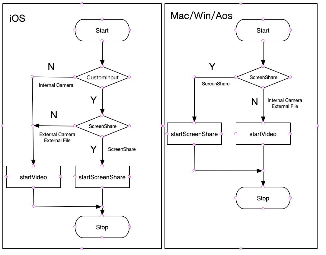
To sum up, iOS custom input can use either mainstream channels to send video (non screen sharing) or secondary channels to send video (screen sharing).
For other platforms, such as Mac, Win, Aos, etc., it is relatively simple. Camera data and screen sharing data come from inside the SDK, while external custom video input data comes from outside.
Key Class Diagram
The single PC architecture mentioned above currently has two RtpTransceivers, one is AudioTransceiver and the other is VideoTransceiver. A new RtpTransceiver will be added to the screen sharing of the secondary stream. A VideoRtpSender will contain a VideoMediaChannel.
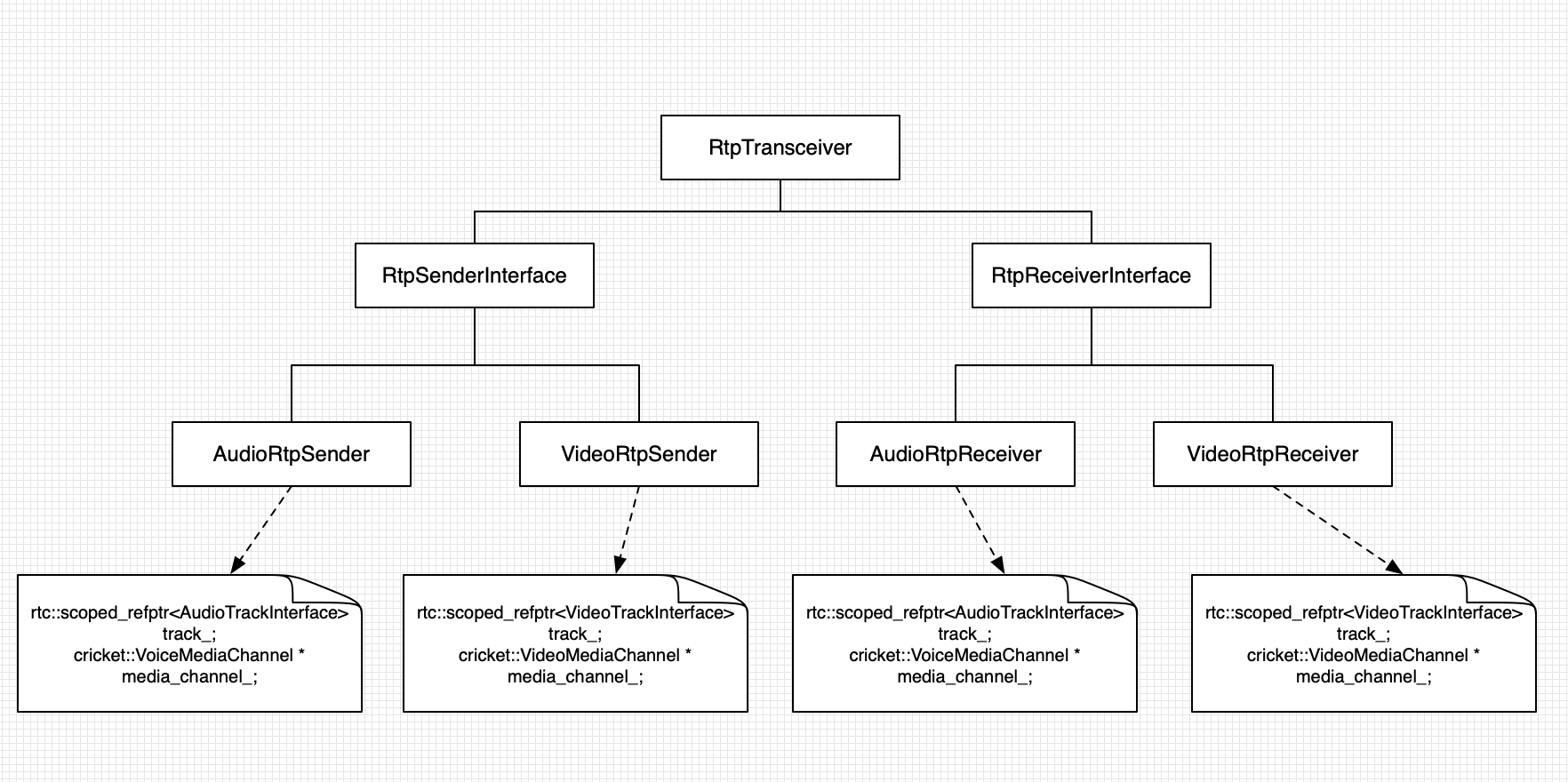
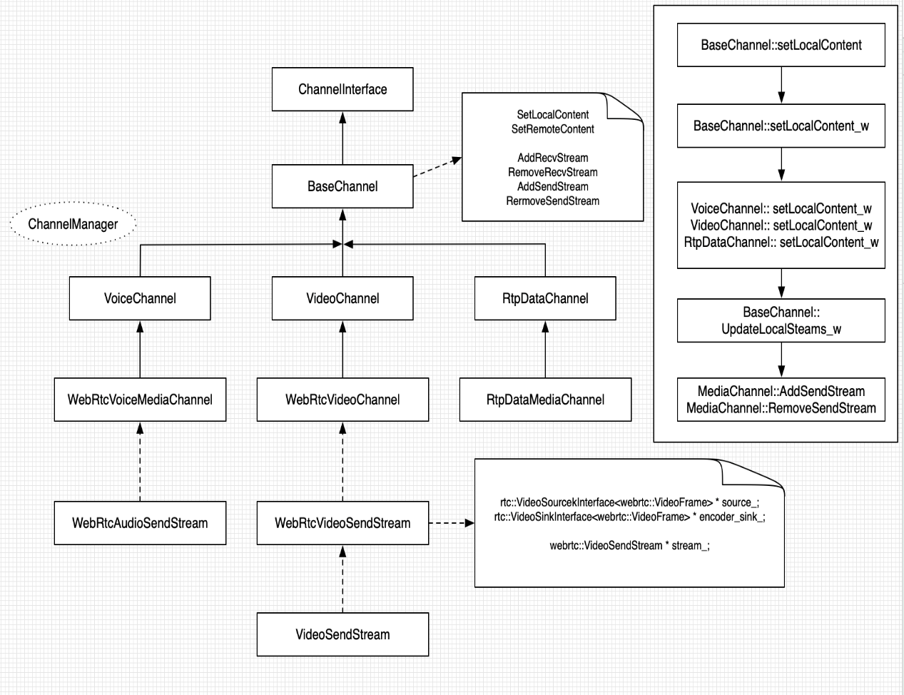
Minor flow change
To implement the auxiliary flow, you need to make some adjustments and restructuring at different levels, as follows:
- The signaling layer needs to support multiple video streams, and mediaType is used to distinguish the above video streams, ScreenShare, and external video streams;
- Reconstruct the management of Capture and Source across platform layers;
- Reconstruct the management of users and rendering canvases. From one UID to one render, the sourceId of one UID corresponds to one render. Each UID may contain two sourceIds;
- The server streaming and recording of interactive live broadcast needs to support the combined recording of mainstream and secondary streams;
- Implementation of congestion control schemes for mainstream and secondary flows;
- Implementation of the rate allocation scheme for the main stream and auxiliary stream;
- Encoder performance optimization of main stream and auxiliary stream;
- Adjustment of PacedSender sending strategy, audio and picture synchronization and other schemes;
- Adjustment of the allocation scheme of QoS downlink code rate of the server;
- Summary of statistical data related to secondary flow;
The following describes the implementation of several important technical points in the whole process.
bandwidth allocation
In weak networks, when video sub streams are needed, we will give priority to the allocation of the code rate to the audio stream, followed by the sub stream, and finally to the mainstream, The overall strategy is to ensure auxiliary flow 。
The main process of bandwidth allocation is as follows:
- The total bandwidth allocation assessed by the congestion control algorithm GCC (hereinafter referred to as CC) of WebRTC will be distributed to audio streams, mainstream streams and secondary streams;
- In the mainstream, the Simulcast module allocates the bit rate of large and small streams. If Simulcast is not enabled, it will directly send the bit rate to the large stream;
The specific process is shown in the figure:
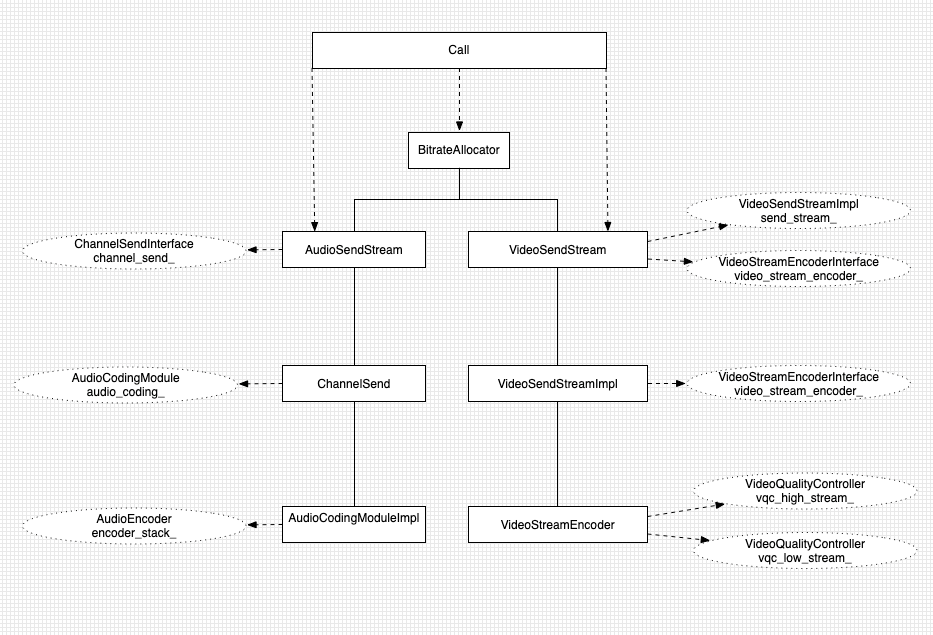
The secondary stream will add a VideoSendStream based on the above figure.
rate allocation
The current process of bit rate allocation is shown in the figure below, which can be summarized as follows:
- The code rate of CC is transferred to Call through the transport controller;
- Then it is allocated to each registered stream (currently the video module) through BitrateAllocator;
- The video module gets the allocated bit rate, which is allocated to fec and retransmission, and the rest is allocated to video encoder bit;
- The video encoder module gets the video encoder bit, which is allocated to large streams and small streams according to our policy;
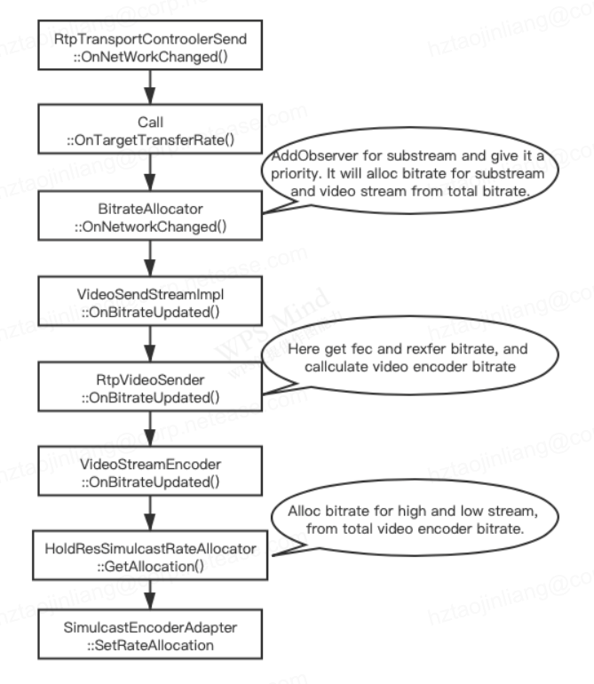
congestion control
In order to realize the function of video auxiliary flow, we need to make relevant changes to the congestion control, mainly through the following four changes:
SDP signaling change
according to RFC 2327 , use "b=<modifier>:<bandwidth value>" to specify the recommended bandwidth. There are two modifiers:
- AS: Single media bandwidth;
- CT: Total session bandwidth, representing the total bandwidth of all media;
At present, the SDK uses the b=AS: method to specify the recommended bandwidth of the camera stream or screen sharing stream, and uses this value as the upper limit of the CC module's estimated value.
The new requirement requires that camera bitstream and screen shared bitstream can be sent simultaneously in the same session. Therefore, the recommended bandwidth value of the whole session should be obtained by adding the recommended bandwidth value of the two channels of media, as the upper limit of the estimated value of the CC module.
WebRTC supports the b=AS: mode (single channel media), which can meet the demand by adding multiple media within WebRTC. WebRTC currently does not support the b=CT: mode, so it is recommended to use the b=AS: mode with relatively few changes.
CC total code rate update strategy
The capability of Pub code stream is updated, and the "maximum bandwidth" is synchronously set to the CC module through SDP mode (b=AS:). When a new media stream is added, the available bandwidth is quickly detected by starting probe fast detection:
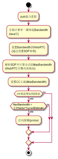
Fast bandwidth assessment
When a media stream is suddenly added, the real bandwidth value needs to be detected quickly, and the probe fast detection algorithm is used to achieve this goal:
- If the detection is successful, the CC estimated value will converge rapidly to the CC upper limit in the bandwidth sufficient scenario, and the real bandwidth in the bandwidth constrained scenario;
- If the detection fails (such as high packet loss rate scenario), the CC estimate will converge slowly, and eventually converge to the upper limit of CC in the bandwidth sufficient scenario, and the real bandwidth in the bandwidth constrained scenario;
Paced Sender Processing
- The sending priority of the secondary stream is the same as that of the mainstream video streams. All video media data are sent smoothly using the budget and packing multiplier methods;
- Add a video stream type, kVideoSubStream = 3, Distinguish from mainstream large and small stream video data;
- During probe fast detection, when the encoded data is insufficient, send padding data to make up for it, so as to ensure that the transmitted code rate meets the requirements;
The following figure shows the actual rate allocation test results:
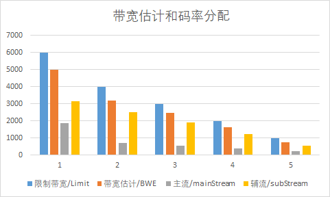
Statistical reporting
The bandwidth statistics report is divided into two parts, which are obtained from MediaInfo and Bweinfo.
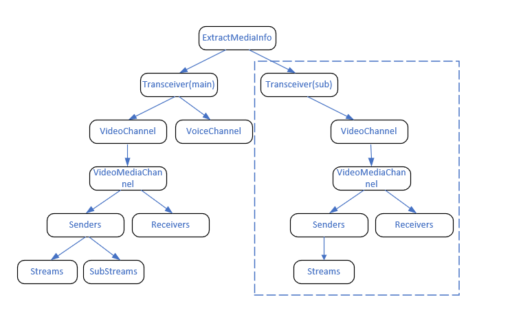
1. MediaInfo acquisition at sender and receiver
The current SDK bandwidth estimation is obtained from MediaInfo. The logic is:
- Traverse all current transceivers to obtain the video_channel and voice_channel of each transceiver, so as to obtain the video_media_channel and voice_media_channel;
- Get the MediaInfo of the current channel according to the getstats of media_channel;
- Put the acquired MediaInfo in verter media_info for reporting;
The main stream and the secondary stream send scenarios at the same time, but only one transceiver is added. Therefore, this logic is applicable to scenarios where the main stream and the secondary stream send scenarios at the same time, as shown in the following figure:
2. Bandwidth estimation information acquisition
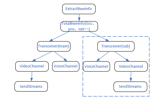
The current SDK bandwidth estimation obtains logic from Bweinfo:
- Obtain gcc, probe probe, etc. to indicate the overall bandwidth information;
- Obtain the bandwidth estimation information related to the voiceChannel and videoChannel of each transceiver (similar to the acquisition of MediaInfo);
The scenario where the primary stream and the secondary stream are sent at the same time only adds transceivers, so this logic applies to the scenario where the primary stream and the secondary stream are sent at the same time, as shown in the following figure:
summary
The above is about the sharing of video auxiliary stream in WebRTC. The technical implementation of video auxiliary stream is shared in detail based on business requirements, technical background and key technology class diagram. You are also welcome to leave a message to communicate with us about WebRTC and audio and video related technologies.
Series Reading


