AutoCad architectural drawing - cad how to draw various walls

Latest answers Change
Q: Returning to Yuantian, Tao Yuanming's Yichen Net
How long is the shelf life of sesame powder 2021-12-16
How to store fresh tremella? 2020-07-08
How to take photos of the elderly 2020-06-09
What to do if the water inlet of the washing machine leaks 2020-03-26
Related recommendations

When is China Grain Day

Can you eat water chestnut in confinement

Can I have a banana on an empty stomach

Can the salt water stored for a long time be used

Is the water sprayed by cicadas poisonous

How to build a fish pond in Xinglu Valley
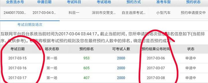
What is the exact time of the successful appointment of subject 1

Do I need to pick up the ticket twice for the connecting flight
Which is better, polished tile or polished tile
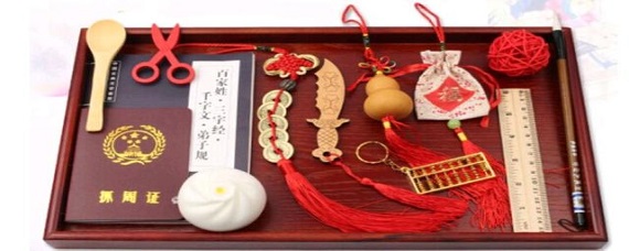
What's the meaning of catching gourd
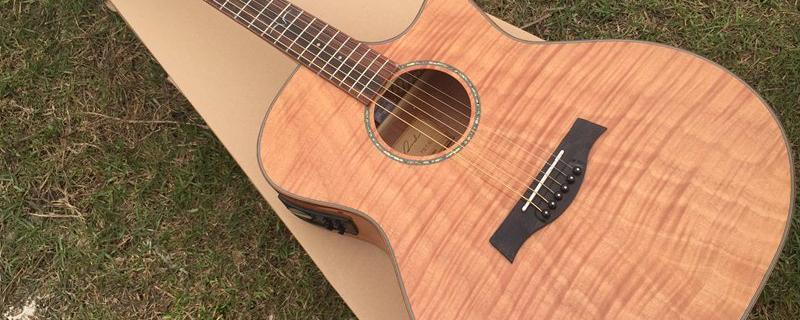
How to maintain the guitar panel
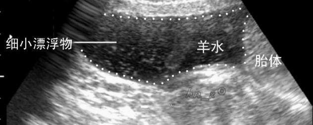
Amniotic fluid is more or less normal in six months
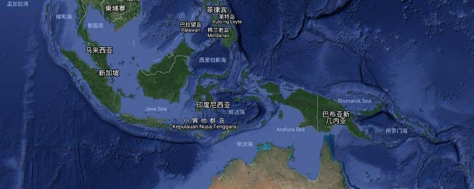
Where is Papua New Guinea