Unveiling the World of Component Diagrams in UML
-
Component: -
Representation: Rectangle with optional compartments. -
Stereotype Text: “<<component>>.” -
Stereotype Icon: Rectangle with protruding smaller rectangles.

-
-
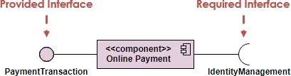
Component Interfaces: -
Provide Interface: Defines public attributes and operations provided by implementing classes. -
Required Interface: Specifies public attributes and operations required by dependent classes. -
Provided and Required Interface:
-
-
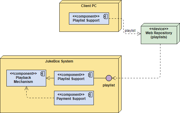
Component Assemblies: Components connect through a ball-and-socket joint, forming subsystems. 
-
Port: Indicates that a component delegates interfaces to an internal class. 
-
Dividing your system into components. -
Displaying interrelationships through interfaces. -
Breaking down components into a lower-level structure.
-
Clarify the diagram’s purpose. -
Add components, grouping them when necessary. -
Include additional elements like classes, objects, and interfaces. -
Establish dependencies between diagram elements.
-
Draw subsystems for logical categorization. -
Utilize the diagram to simplify the high-level system view.
-
Order Processing System: -
Offers a holistic view of components involved in an online store.

-
-
Ticket Selling System: -
Highlights components like ticket seller, credit card processor, and database.

-
-
Store Component: -
Demonstrates nested component structure.

-
-
White-Box View: -
Explores the internal composition of components.

-
-
Deployment Diagram Integration: -
Depicts the physical deployment of software components.

-
Conclusion
Component Diagram Templates


