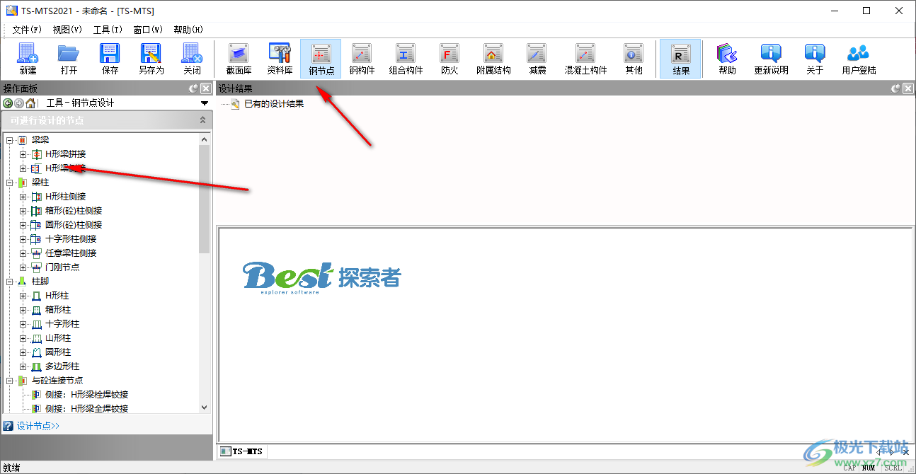
TS-MTS steel structure calculation toolbox can help users quickly design steel nodes, steel members, composite members, ancillary structures, and concrete members on the computer. You can directly start the software to display the design functions in the top area. You can directly click on steel member design, and then display the design tools related to steel members in the left area. You can choose to design platform beams Each design tool provides basic parameter input for crane beam, crane track, single span component and multi span component. You can input control parameters yourself and set section parameters to generate calculation sheets and CAD drawings on the software. The design process is relatively simple. If you need this software, download it!
software function
1. Steel node design:
TS-MTS toolbox supports beam beam connection, beam column connection, column foot connection, connection with concrete, column column connection, truss/support connection And part calculation. Each type has a variety of specific forms to choose from, including most of the actual projects The node type of the point. It supports checking calculation and automatic design, can generate and export detailed calculation sheets, and can generate exported node design drawings.
2. Steel member design:
Steel member design of TS-MTS toolbox includes beam member, column member, support member, truss member, purlin member and shape Steel design. The beam member design provides independent design of platform beam, crane beam, crane track, single span member and multi span member; Columnar structure The design of components provides uniaxial symmetric I-beam tension bending bending members, biaxial symmetric I-beam tension bending bending members, square steel tube tension bending bending bending members and Design of wind resistant column; Support member design provides roof support, inter column support and corner brace design; Truss member design provides roof truss Design of bracket truss, horizontal truss, vertical truss and skylight truss; Purlin component design provides simply supported roof purlin, continuous roof purlin and simply supported wall Purlin, continuous wall purlin, truss purlin design; Section steel design includes section steel simply supported beam, section steel composite beam, section steel crane beam Design of simply supported purlins and wind resistant columns. Detailed calculation sheets can be generated and exported. Some modules support the plotting function.
3. Composite member design:
The composite member design of TS-MTS toolbox includes the design of rectangular steel tube concrete column, round steel tube concrete column, I-shaped steel reinforced concrete rectangular column, cross shaped steel reinforced concrete rectangular column, I-shaped steel reinforced beam and simply supported composite beam. Detailed calculation sheets can be generated and exported. Some modules support plotting Function.
4. Auxiliary structure design:
The auxiliary structure design of TS-MTS toolbox includes the design of single running inclined ladder and overhanging canopy in the design of steel stairs.
TS-MTS toolbox supports the design of single running inclined ladder. It can design ladder beam, upper platform beam, lower platform beam, tread, upper platform plate and lower platform plate, generate and export detailed calculation sheets, and support the function of outputting internal force diagrams.
Fixed deflection calculation can generate and export detailed calculation sheet, and support the function of outputting internal force diagram.
5. Shock absorption related design:
The shock absorption related design of TS-MTS toolbox currently only includes literature database and BRB design.
The TS-MTS toolbox literature database includes the design manual of TJ buckling restrained braces, technical regulations for energy dissipation and seismic reduction of buildings, technical regulations for the application of TJ buckling restrained braces and other information on building seismic reduction.
TS-MTS2019 toolbox BRB design includes a support tonnage range estimation tool, which can calculate the yield bearing capacity range and the support appearance reference value of the support according to the support equivalent area in the structural model.
6. Concrete component design:
The composite member design of TS-MTS toolbox includes rectangular column and circular column design. Detailed calculation sheets can be generated and exported. Some modules support the plotting function.
7. Other relevant designs:
Other relevant designs of TS-MTS toolbox include roof drainage design.
The TS-MTS toolbox supports roof drainage design, that is, the design determines the size of the gutter and the layout spacing and diameter of the downpipe, and can generate and export detailed calculations.
8. Database query:
The database query of TS-MTS toolbox includes: member load library, load case library, material library, crane garage, profiled steel plate library, bolt library, reinforcement library, parts steel plate library, anchor parts library, stud library, foundation database, section library, seismic library, wind pressure, snow pressure, basic air temperature library and other engineering databases. TS-MTS2019 The toolbox contains a large amount of database information according to the existing standards and industry production status, and users can customize the addition.
Software features
1. TS-MTS steel structure calculation toolbox provides professional calculation function and can generate calculation sheets
2. Start the software and click a design function in the top area to use
3. The database function is supported. The software can query the design data and view the material data
4. Support Level A common bolt library, Level B common bolt library, Level C common bolt library, friction type high-strength bolt library
5. Rebar library: default slab reinforcement scheme, foundation slab reinforcement scheme, only plain reinforcement scheme, only ribbed reinforcement scheme
6. Name of part steel plate warehouse: Q235 steel plate warehouse: there are 39 part steel plates in the part steel plate warehouse
7. Name of anchor bolt warehouse: double nut hook anchor bolt warehouse
Anchor bolt anchoring mode: end hook
Anchor bolt connection mode: double nut bolting
There are 20 anchor bolts in the anchor bolt warehouse
8. Name of stud library: composite beam stud library
Stud production standard: GB/T 10433
Design value of ultimate tensile strength of stud: fu=400MPa
There are 93 studs in the stud library
9. Support weld joint group, anchor bolt group, bolt group, embedded parts and rear anchor, pin shaft
10. Control parameters: non low hydrogen welding or low hydrogen welding method with preheating is adopted for fillet weld
11. Milling, static load bearing, indirect dynamic load bearing and direct dynamic load bearing can also be selected
12. Bottom slab concrete setting: C25 bottom slab concrete. Considering the local compression of concrete, increase the strength design value
usage method
1. Directly install the TS-MTS steel structure calculation toolbox to the OA computer
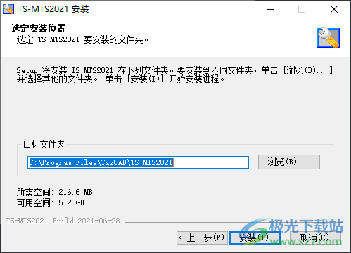
2. Set the software installation address C: Program FilesTszCADTS-MTS2021
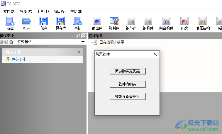
3. Enter the TS-MTS steel structure calculation toolbox to purchase software, and enter the mall to purchase
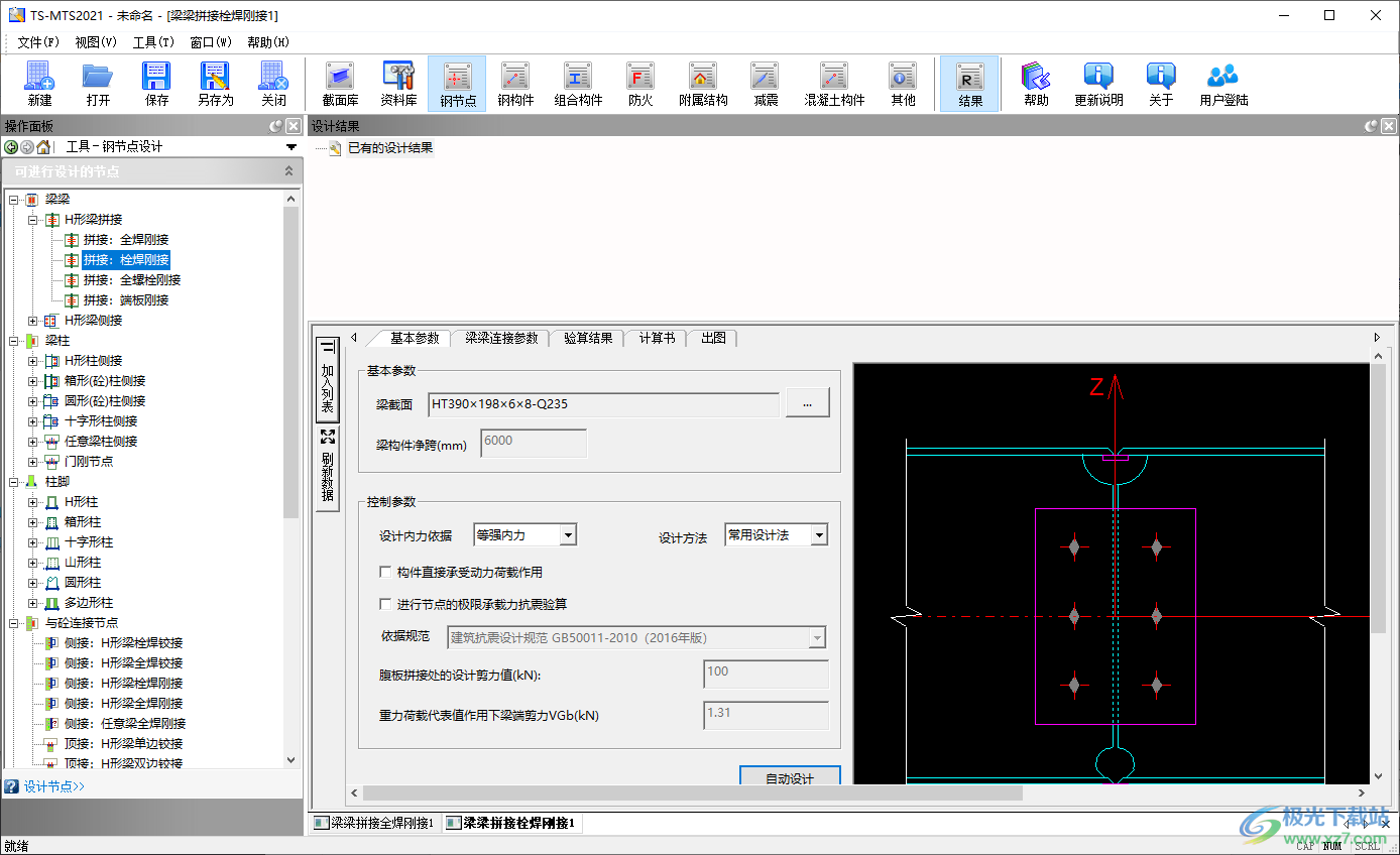
4. The design function is displayed on the top of the software. You can click the steel node design to display the design parameters on the left
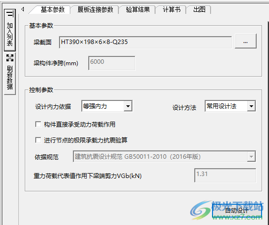
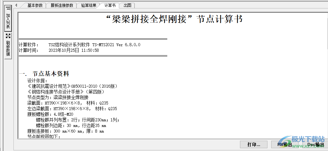
5. Basic parameters: beam section HT390 × 198 × 6 × 8-Q235, clear span of beam member (mm) 6000
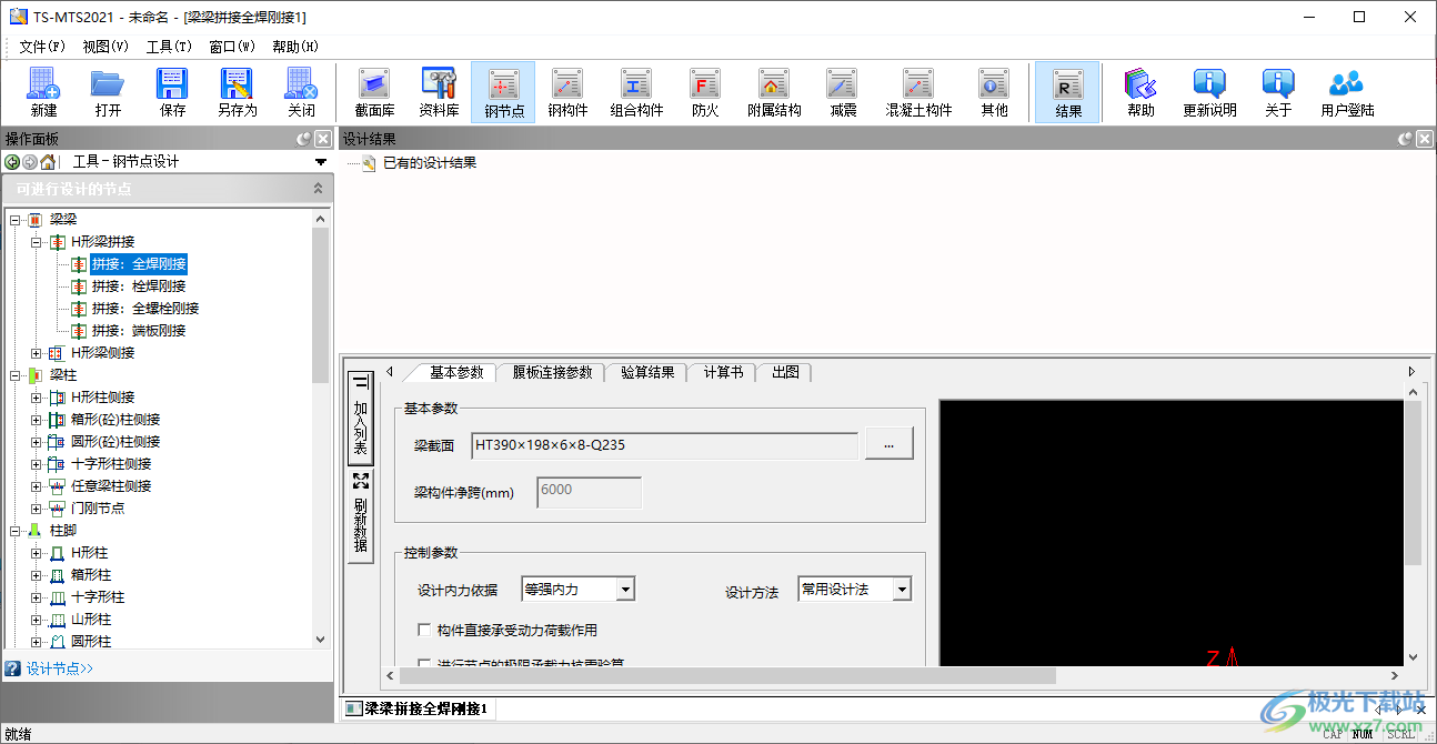
6. Control parameters
Design internal force basis: equal strength internal force
Design method: common design method
Members directly bear dynamic load
Conduct seismic checking calculation of ultimate bearing capacity of joints
Code: Code for Seismic Design of Buildings GB50011-2010 (2016 version)
Shear force at beam end under representative value of gravity load VGb (kN): 1.31
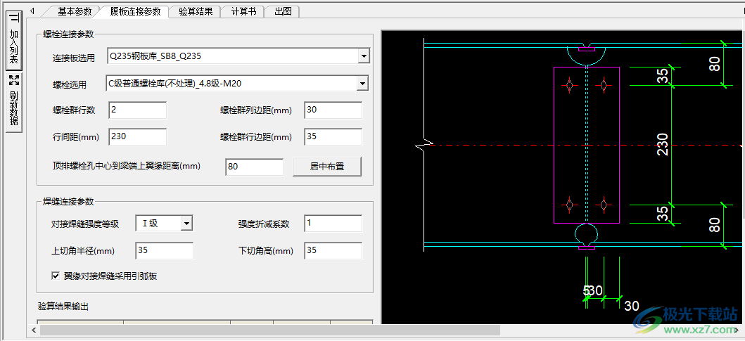
7. Bolt connection parameters
Q235 steel plate warehouse SB8Q235 is selected as the connecting plate
Grade C ordinary bolt library (not treated) Grade 4.8 - M20 is selected for bolts
Number of bolt group rows 2
Edge distance of bolt group (mm) 30
Line spacing (mm) 230
Row edge distance of bolt group (mm) 35
Distance from top row bolt hole center to upper flange of beam end (mm) 80
Centered layout
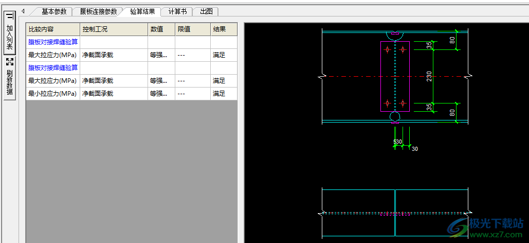
8. Comparison content
Checking calculation of web butt weld
Maximum tensile stress (MPa)
Checking calculation of web butt weld
Maximum tensile stress (MPa)
Minimum tensile stress (MPa)
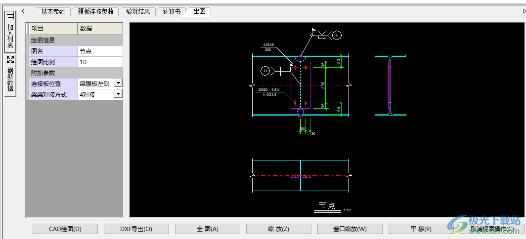
9. Generate the calculation sheet, and directly save the calculated data as doc for future addition to the project file
10. Drawing function, can directly save the generated CAD drawings in the software, and can export to DXF format
Update log
V6.8 Update Description
1.1 Error in editing basic seismic combination of load case library
1.2 Error in checking calculation of bearing capacity of side bolted and welded rigid fillet weld of H-shaped beam
1.3 The schematic diagram is incorrect when modifying the section of the door rigid node
1.4 Modification of subscript for fillet weld calculation of door rigid joint
1.5 Modification of local stability calculation of T-shaped section of platform beam
1.6 The strength limit of cold formed thin-walled steel Q355 of platform beam is incorrect
1.7 Modification of concentrated load schematic diagram of platform beam
1.8 Adding direction control to platform beam
1.9 The results of single span member stability calculation are incorrect
1.10 When the control "Y axis of the section is in the vertical plane" is not checked, the calculation result is incorrect
1.11 Adding and editing crane beam
1.12 Modification of connection type at upper end of wind column
1.13 Logic error between overall stability calculation and "wind column wall purlin elevation" control
1.14 Grade Q355 strength limit of simply supported purlin is incorrect
1.15 Crash when editing "advanced parameter setting" of simply supported roof purlin
1.16 The span of simply supported roof purlin is wrong when it is cantilevered
1.17 Deflection limit of continuous wall purlin cannot be saved
1.18 The strength limit value of simply supported composite beam in service stage is incorrect
1.19 Add fire protection calculation
1.20 Add the fire protection calculation of axial stressed members
1.21 Add fire protection calculation for flexural members
1.22 Add fire protection calculation for tension and compression bending members
1.23 Modify the internal force diagram of steel stairs without platforms 1.24 Modify the detail drawing of exposed and shoe beam column foot nodes, add anchor bolt schematic diagram, and adjust the layout of drawings
1.25 Modify the judgment method for the calculation condition of the diameter of round outer cylindrical column base
1.26 Modify the problem of unsaved setting parameters of outsourced and embedded column base stud groups
1.27 The symbol of individual axial force in the calculation sheet of shear resistance of column base node is changed from N to Nz
1.28 Modify the column and base plate weld names in the column base node calculation sheet
1.29 Modification of stud layout and marking in detail drawing of outsourced column base node
1.30 Modify the text of node detail in outsourced and embedded column base calculation sheets
1.31 Modify the internal force expression details in the calculation sheet of beam bolt welding and full bolt rigid connection nodes
1.32 Modify the problem that the web of beam beam side connection and beam column hinge joint should bear all axial forces and should not be distributed by area
1.33 Revise the automatic design method of beam beam splicing and side rigid connection node program, and the bending moment problem is not considered when the web should bear the bending moment
1.34 Modify the inconsistency between individual parameters in the check calculation result list of beam beam spliced bolted rigid joints and those in the calculation sheet
1.35 The calculation problem that the ultimate bending bearing capacity of flange plate of all bolt rigid connection joint of beam beam splicing should be taken as net section
1.36 Details of calculation sheet when modifying embedded parts and rear anchor bars with hooks
1.37 Modify the load value, interface details and load name in the calculation sheet of steel stairs
1.38 Revise the calculation results of the weakening ratio of the section of the bolted rigid joint on the front of the column to judge the output error of the calculation sheet
1.39 Modify the internal force symbol and value of fillet weld strength checking calculation of beam, beam column, and concrete joint beam and connecting plate
1.40 Adjust the text position of the detail drawing of the connection node with the concrete
1.41 Check calculation of fillet weld between beam and connecting plate of full welded rigid joint beam and beam side connection, without considering the eccentric bending moment caused by shear force at the weld
1.42 VGB should not be grayed out and uneditable when checking the ultimate bearing capacity of beam column rigid connection joints
1.43 Problems in calculation interface adjustment of bolt group of steel node parts, miniature display repair and calculation of single connecting plate and double connecting plate
1.44 Restoration of the diagram for checking and calculating the bearing capacity of steel member column bracing under earthquake combination
1.45 Steel node_truss support node_internal force input problem in welding calculation of repair side cross connecting plate
1.46 Steel node_truss support node_minimum spacing inspection and interface adjustment of circular tube and circular tube intersecting branch
1.47 Unit correction of calculation sheet of steel member support checking calculation
1.48 Steel node _ connection node with concrete _ height limit of bolted and welded rigid beam column section of side connected H-beam is relaxed
1.49 Steel node_beam column_H-shaped column side connected with H-shaped weak shaft full welded hinge