1. Introduction
In the general asynchronous AC motor drive, the motor is mostly in the electric state, and the motor needs to absorb energy from the power grid. However, due to different loads, the asynchronous motor may be in the power generation state when some loads require rapid braking of the motor, or when the load has a certain position potential energy. If the motor is directly connected to the power grid, electric machinery The generated electricity feeds back to the power grid, but this has a greater impact on the power grid. If the motor is driven by the frequency converter, the frequency converter has an intermediate energy storage link, and its energy storage is limited, so the motor power generation status has a greater threat to the frequency converter. When the frequency converter deals with the regenerative power generation of the motor, there are many braking methods, such as energy consumption braking, energy storage braking, feedback braking, etc. For the energy consumption braking method, the electricity generated by the motor will be wasted, and the energy consumption resistance will often be damaged; The energy storage in the energy storage braking method is also limited, which also poses a threat to the frequency converter. Energy feedback is a good way to deal with regenerative power generation and braking. It ensures the safety of the frequency converter, saves energy, and enhances the braking function of the motor. This paper will discuss some technical problems of energy feedback.
2. Simple implementation
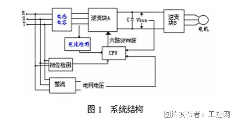
The system structure is shown in Figure 1 below, which consists of the control system of LC filter, inverter block A, bus capacitor C, inverter block B and inverter block A.
Generally, the motor works in the electric state, and the inverter block A is used for rectification, and in the power generation state, it is used for inverter feedback. When the motor generates power, the rectifier voltage is added to the bus capacitor C through the diode rectification of inverse parallel connection of IGBT in inverter block B. If the generating power is large, the bus voltage will rise, directly threatening the safety of the whole system, In this way, the inverter block A needs to be started to feed the surplus energy back to the power grid through inductance and capacitance. The inductance will bear the difference between the DC bus voltage and the grid line voltage, while the inductance will buffer the reactive power of harmonics.

To complete feedback braking, three tasks need to be completed: 1) detect when the voltage begins to feedback; 2) Keep feedback braking in the same frequency and phase with the power grid; 3) Limit the size of feedback current during feedback braking.
2.1 Voltage detection
In the voltage detection, it mainly detects the DC bus voltage and the grid voltage. When detecting the grid voltage, it is generally necessary to consider the fluctuation of the grid. According to the DC voltage that can be borne by the intermediate link of the inverter, when the feedback braking is used, the grid is allowed to fluctuate upwards by+20%. Therefore, in the DC voltage detection, the voltage value is (1.2 * √ 2) When the effective value of grid line voltage is times, inverter block A can be started to work and enter the feedback braking state.
2.2 Grid frequency and phase detection
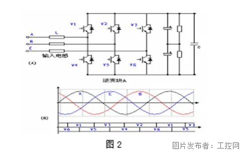
In feedback braking, the key to effectively feedback energy is to ensure that it is in the same frequency and phase with the power grid, and to ensure that the power grid outputs negative current when it outputs positive voltage. Secondly, try to select the high voltage section of grid line voltage during feedback, as shown in Figure 2, so that larger energy feedback power can be obtained when the feedback current is fixed.

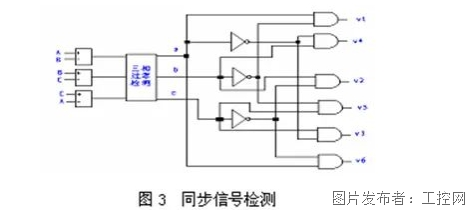
Set the switch state of the power device in inverter block A to be synchronized with the power grid. The synchronization signal is shown in Figure 2 (B). The following is a simple synchronization signal control method, which can simply obtain the synchronized square wave pulse of V1-V6.

2.3 Control of feedback current
In the feedback braking, it is also important to control the feedback current reasonably. The feedback current must meet the requirements of energy feedback power. If the system feedback power is less than the output power of the motor in the power generation state, the voltage on the DC bus of the inverter will continue to rise. Since the grid voltage is fixed, the size of the system feedback power is determined by the size of the feedback current. In addition, the size of the feedback current must be controlled within the rated range of the IGBT used.
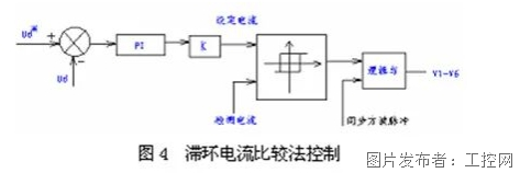
During feedback braking, the feedback current changes rapidly, so it is necessary to adopt an effective control mode, which is generally controlled by hysteresis current comparison method, as shown in the following block diagram 4:

3. Engineering application
We used this feedback braking method to install a 380V75KW load lifting inverter in Xinjiang Manas Yong'an Coal Industry Co., Ltd. From the perspective of field application:
When feedback braking, the current can reach about 40A. The frequency converter adopts the hysteresis current comparison method to feedback braking. The bus voltage is higher than the set reference voltage, that is, the feedback. When it is higher than 645V, the feedback braking is started, so that the energy can be fed back to the power grid, thus ensuring the safe operation of the frequency converter. By detecting the bus voltage, no large voltage fluctuation can be seen. The waveform fed back to the power grid is relatively good. After proper LC filtering is adopted, the power grid will not be polluted basically, and the filtering effect is good. Energy saving effect is also obvious. Compared with power frequency, the comprehensive power saving rate is about 30%. The 75KW hoist can be directly driven by ordinary squirrel cage motor after frequency conversion, which can smoothly regulate the speed without winding motor Motor price It is about 1/3 cheaper than the wound motor, so it can reduce the user's investment cost and is more convenient to maintain. After the adoption of frequency conversion speed regulation, the speed range switching AC contactor and speed regulation resistance used by the original power frequency are dropped, which greatly improves the operating environment of workers, makes the speed regulation smooth, reduces the impact on the power grid and gear shifting, and the current changes smoothly, which is incomparable to the original power frequency state.
4. Conclusion
If the inverter drives a hoist load, the inverter should have multiple braking means, and feedback braking is an important one. The feedback braking has been successfully applied to the special inverter for Fengguang elevator produced by our company, and good results have been achieved. The waveform of the feedback energy must be good and the feedback phase must be accurate, otherwise the feedback will impact the power grid. The technical key lies in this.


